
Creating a Test Plan - MIC LTE-CA
The MIC LTE-CA option is used for Japan MIC technical conformity certification testing of terminal products supporting LTE Carrier Aggregation.
Basic Settings
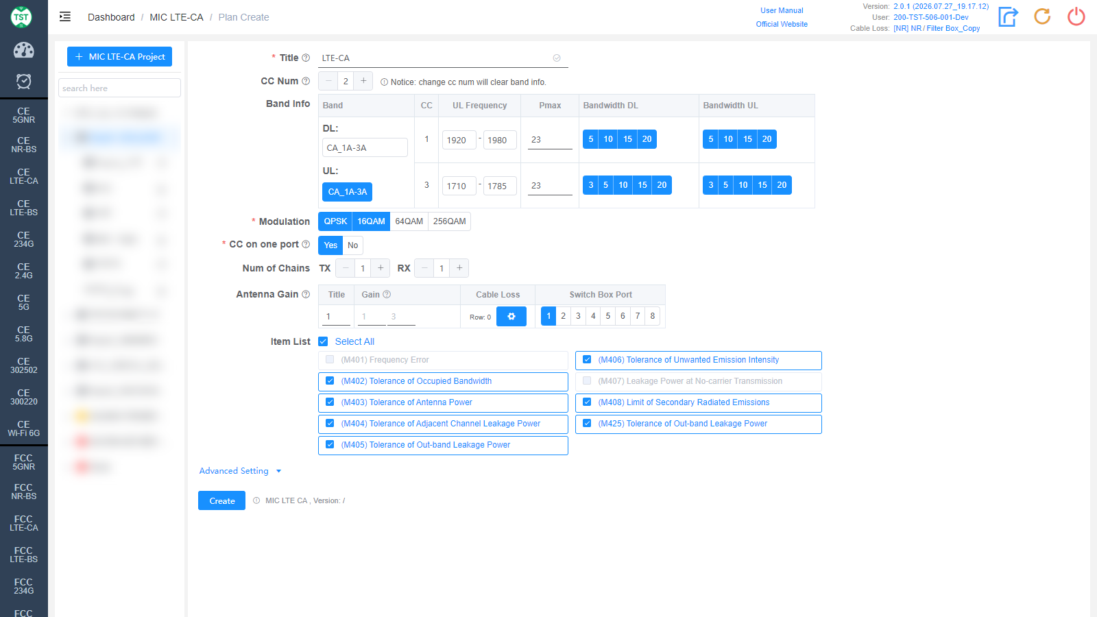
Title: Test plan name, entered by the user.
CC Num: Number of carriers, currently only 2 is supported. Note: changing CC Num will clear the Band Info.
Band Info: Select the CA band combination supported by the product (e.g., Japanese combinations CA_1C / CA_1A-3A / CA_1A-8A / CA_40C). The table then lists the DL / UL rows:
CC: Band of each Component Carrier.
UL Frequency: Uplink frequency range (MHz), auto-filled.
Pmax: Maximum transmit power (dBm), default 23.
Bandwidth DL / Bandwidth UL: Bandwidths (MHz) supported by each carrier, multi-select. Available options vary with the band combination.
Modulation: Modulations supported by the product (required), multi-select: QPSK / 16QAM / 64QAM / 256QAM, QPSK + 16QAM selected by default.
CC on one port: Whether the two carriers are output from the same antenna port (required): Yes / No.
Num of Chains: Number of transmit (TX) and receive (RX) chains.
Antenna Gain: Antenna gain and cable loss configuration:
Title / Gain: Antenna number and gain (dBi) for each carrier band.
Cable Loss: Cable loss from the product's antenna port to the Switch Box or spectrum analyzer. How to Create Common Cable Loss.
Switch Box Port: Port number of the switch connected to the antenna.
Item List: Test items included in MIC LTE-CA. Items not applicable to CA (e.g., M401 / M407) are greyed out automatically:
(M401) Frequency Error (greyed out for CA)
(M402) Tolerance of Occupied Bandwidth
(M403) Tolerance of Antenna Power
(M404) Tolerance of Adjacent Channel Leakage Power
(M405) Tolerance of Out-band Leakage Power
(M406) Tolerance of Unwanted Emission Intensity
(M407) Leakage Power at No-carrier Transmission (greyed out for CA)
(M408) Limit of Secondary Radiated Emissions
(M425) Tolerance of Out-band Leakage Power
Advanced Setting
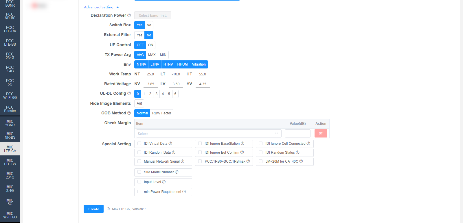
All settings in Advanced Setting can generally be kept at their default values. Adjust them only when the test results are abnormal or there are special test requirements.
Declaration Power: Declared power (dBm) for each carrier, defaults to the Pmax in Band Info. Displayed after a band combination is selected.
Switch Box: Whether to use a Switch Box (RF switch).
External Filter: Whether an external filter is used in the RF path.
UE Control: Whether the software automatically controls the sample, default OFF.
TX Power Arg: TX power evaluation method: AVG / MAX / MIN.
Env: Environmental conditions, multi-select: NTNV / LTNV / HTNV / HHUM / Vibration.
Work Temp: Temperatures (°C) for the environmental conditions, default NT 25.0 / LT -10.0 / HT 55.0.
Rated Voltage: Voltages (V) for the environmental conditions, default NV 3.85 / LV 3.50 / HV 4.35.
UL-DL Config: LTE TDD uplink-downlink subframe configuration (0 ~ 6). Only relevant for TDD.
Hide Image Elements: Elements to hide in report images (e.g., the Ant marker).
OOB Method: Measurement method for M405 / M425 Tolerance of Out-band Leakage Power: Normal / RBW Factor. The default value can be changed on the Setting page.
Check Margin: Test margin check. Select an Item and fill in Value(dB); results with a margin smaller than the set value will be flagged.
Special Setting: Special settings. Options prefixed with [D] are debug options:
[D] Virtual Data / [D] Ignore BaseStation / [D] Ignore Cell Connected / [D] Random Data / [D] Ignore Eut Confirm / [D] Random Status: Debug options.
Manual Network Signal: Set the Network Signal manually.
PCC:1RB0+SCC:1RBmax: If selected, the original PCC:1RB0+SCC:1RB0 or PCC:1RBmax+SCC:1RBmax RB allocations in all test items will be changed to PCC:1RB0+SCC:1RBmax.
5M+20M for CA_40C: Use the 5 MHz + 20 MHz bandwidth configuration for CA_40C.
SIM Model Number: SIM card model, default P0250. For MT8000 / MT8821.
Input Level: Input level (dBm).
min Power Requirement: Minimum power requirement, default 0 dBm.
Corresponding software option: MIC LTE CA