Creating a Test Plan - CE 2.4G
The CE 2.4G option is used for EU CE (RED) certification testing of unlicensed products in the 2.4 GHz band (per EN 300 328), covering both transmitter and receiver (Adaptivity / Blocking) parameters. When creating a test plan, select the Type (technology) first: WLAN / Bluetooth / BLE / Zigbee / Proprietary. Each type is described separately below.
WLAN
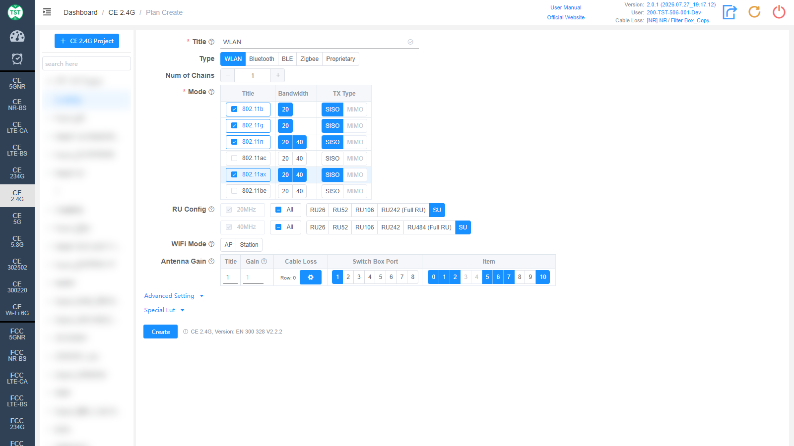
Title: Test plan name, entered by the user, e.g., WLAN / BT / WiFi-Ant1.
Type: Technical category, select WLAN here.
Num of Chains: Number of transmit chains (antennas) the product has.
Mode: Modes supported by the product (required): 802.11b / g / n / ac / ax / be. After checking a mode, select the corresponding Bandwidth (20 / 40 MHz) and TX Type (SISO / MIMO).
RU Config: RU (Resource Unit) configurations supported by 802.11ax / be devices. The Full RU of each bandwidth is required; select the other RU configurations according to the product's actual support. Displayed after 802.11ax / be is checked.
WiFi Mode: WiFi role of the EUT:
AP: The device acts as the "wireless access center point", providing the wireless network signal.
Station: The device acts as a client, accessing the wireless network through a wireless connection.
Antenna Gain:
Title: Antenna number, named sequentially by default as 1, 2, 3, 4..., or manually input other names according to customer requirements.
Gain: Gain of each antenna in the corresponding band (Band).
Cable Loss: Cable loss of the RF cable from the product's antenna port to the Switch Box (RF port of the switch) or the SA (spectrum analyzer). How to Create Common Cable Loss.
Switch Box Port: Port number of the switch connected to the product's antenna, e.g., Ant1 connected to port 1, Ant2 connected to port 2.
Item: Test items for each antenna; the numbers correspond as follows:
(C2400) Duty Cycle - SA
(C2401) RF Output Power, Duty Cycle, Tx-sequence, Tx-gap, Medium Utilization
(C2402) Power Spectral Density
(C2403) Accumulated Transmit Time, Frequency Occupation And Hopping Sequence
(C2404) Hopping Frequency Separation
(C2405) Adaptivity (Channel Access Mechanism)
(C2406) Occupied Channel Bandwidth
(C2407) Transmitter Unwanted Emissions In The Out-Of-Band Domain
(C2408) Transmitter Unwanted Emissions In The Spurious Domain
(C2409) Receiver Spurious Emissions
(C2410) Receiver Blocking
The software preselects the default test items according to the characteristics of each technology. Note: In some cases, test parameters are mutually referenced between items; it is recommended to create the test plan with the default items.
Bluetooth
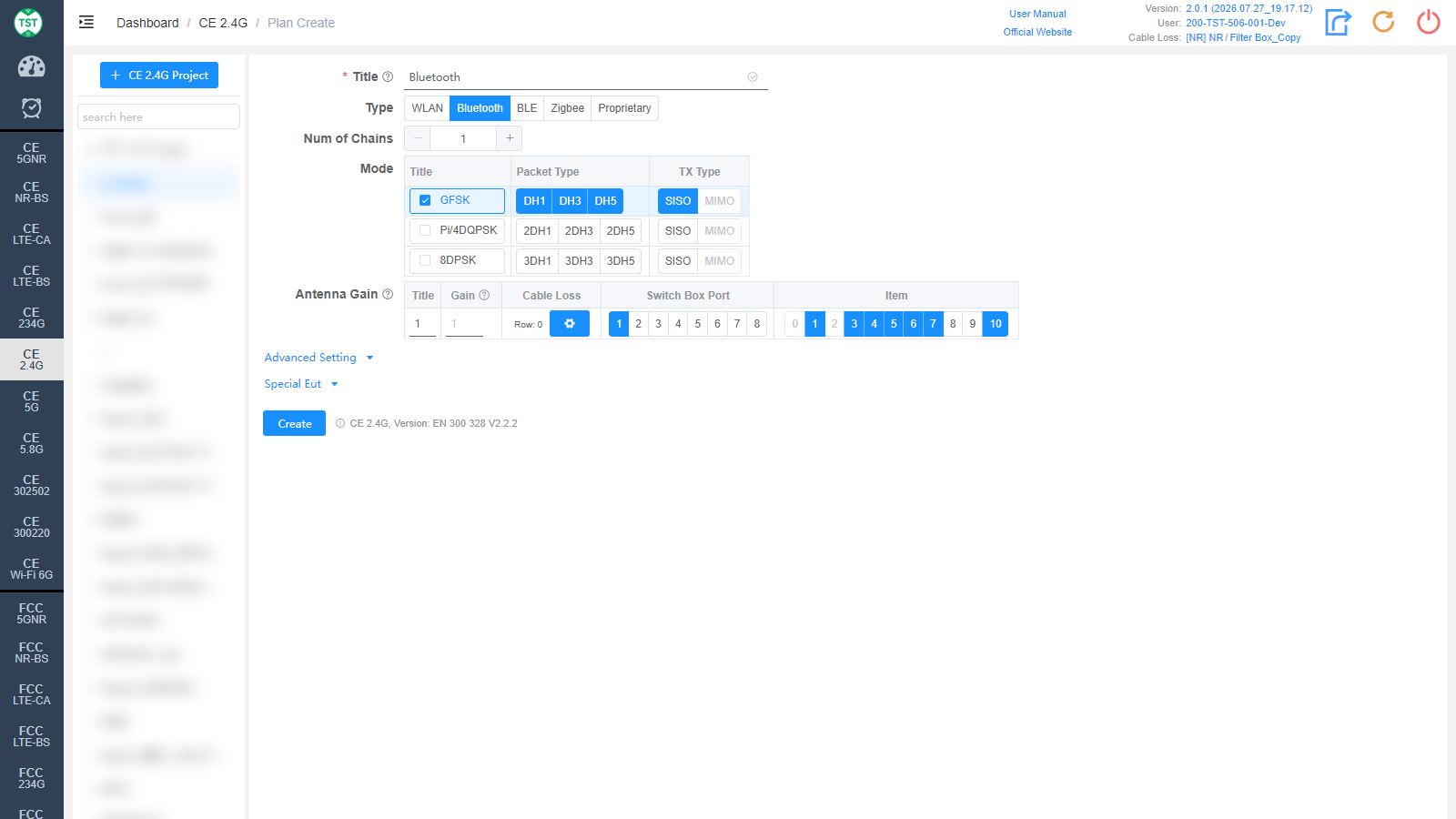
Type: Technical category, select Bluetooth here.
Num of Chains: Number of transmit chains the product has; Bluetooth currently supports only a single antenna.
Mode: Modulations and packet types (Packet Type) supported by the product:
GFSK: BR (Basic Rate), packet types DH1 / DH3 / DH5.
Pi/4DQPSK: EDR 2M, packet types 2DH1 / 2DH3 / 2DH5.
8DPSK: EDR 3M, packet types 3DH1 / 3DH3 / 3DH5.
Antenna Gain is the same as WLAN and is not repeated here.
BLE
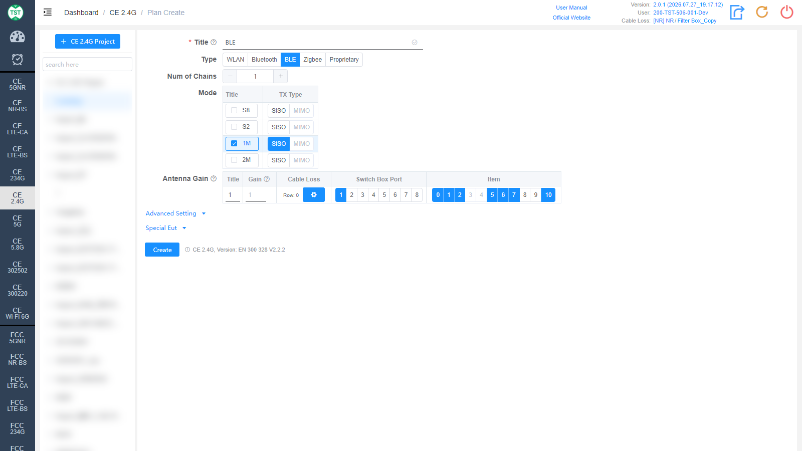
Type: Technical category, select BLE here.
Num of Chains: Number of transmit chains the product has; BLE currently supports only a single antenna.
Mode: Modes supported by the product: S8 / S2 / 1M / 2M. In protocol versions before BT 5.0, BLE only had the 1Mbps rate. Starting from version 5.0, in addition to keeping the 1Mbps rate, two new rates for Long Range scenarios targeting IoT products, S8 and S2 (corresponding to 125kbps and 500kbps respectively), were added, along with the 2Mbps rate for high-bandwidth scenarios. Among them, the 1Mbps rate is mandatory for version 5.0 and above, while the other three rates are optional. In addition, the S8 and S2 rates are implemented by adding FEC (Forward Error Correction) on top of 1Mbps, and their symbol rate is still 1Mbps, so in terms of actual test results, the results of the S8, S2 and 1M modes are basically identical. Therefore, for products that support all three rates, generally only the 1M mode is tested (if S8, S2 and 1M are all selected, the software will test the three modes separately).
Antenna Gain is the same as WLAN and is not repeated here.
Zigbee
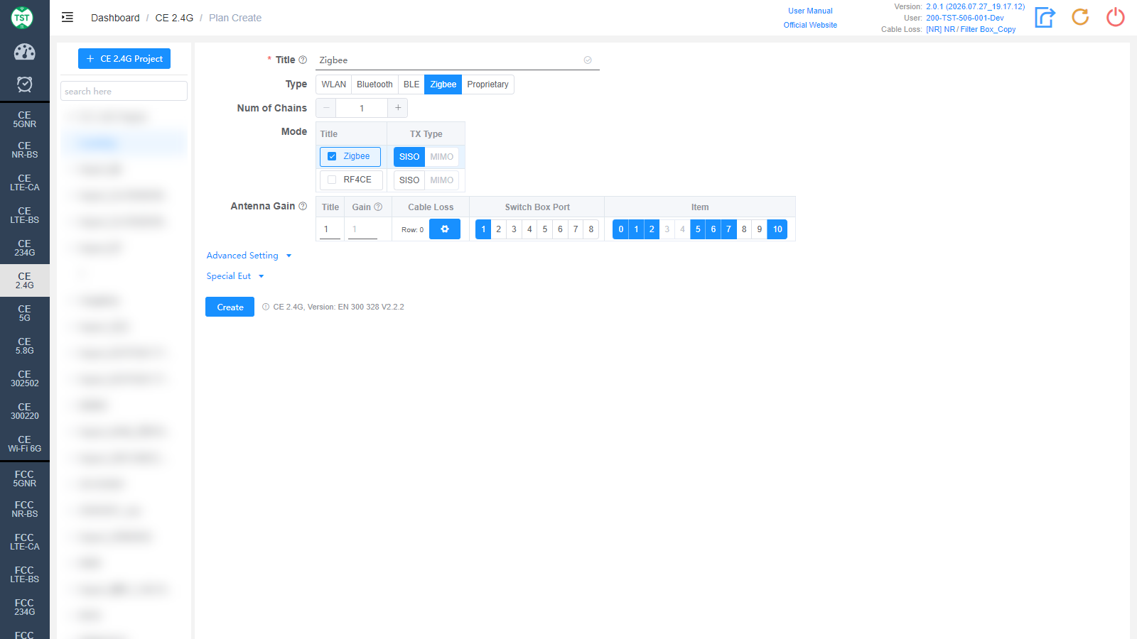
Type: Technical category, select Zigbee here.
Num of Chains: Number of transmit chains (antennas) the product has.
Mode: Modes supported by the product: Zigbee / RF4CE.
Antenna Gain is the same as WLAN and is not repeated here.
Proprietary
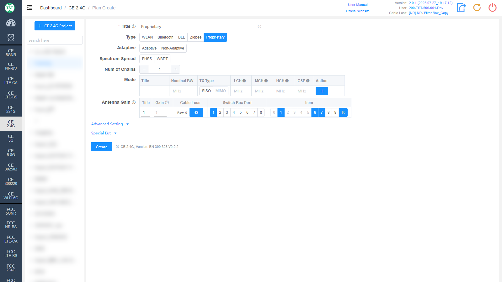
Type: Technical category, Proprietary (custom product).
Adaptive: Whether the product is an adaptive device: Adaptive / Non-Adaptive. Affects the applicable test items and limits.
Spectrum Spread: Select the spectrum spreading method:
FHSS: Frequency Hopping Spread Spectrum, which transmits the signal by rapidly switching (hopping) among a set of known frequencies, thereby spreading the signal over the spectrum. Its advantages are reduced interference and improved security.
WBDT: WideBand Direct Transmission, a wideband direct-sequence spread spectrum (DS-SS) technique that achieves stronger interference resistance by transmitting the signal over a wider bandwidth.
Num of Chains: Number of transmit chains (antennas) the product has.
Mode: Custom mode table:
Title: Mode number; other names can be manually input according to customer requirements.
Nominal BW: Sets the nominal bandwidth occupied by the signal on the spectrum.
TX Type: Transmission type, SISO / MIMO.
LCH / MCH / HCH: Low / middle / high channel frequency settings (MHz).
CSP: Channel Spacing.
Action: Used to add / delete mode configuration rows.
Antenna Gain is the same as WLAN and is not repeated here.
Advanced Setting and Special Eut Settings
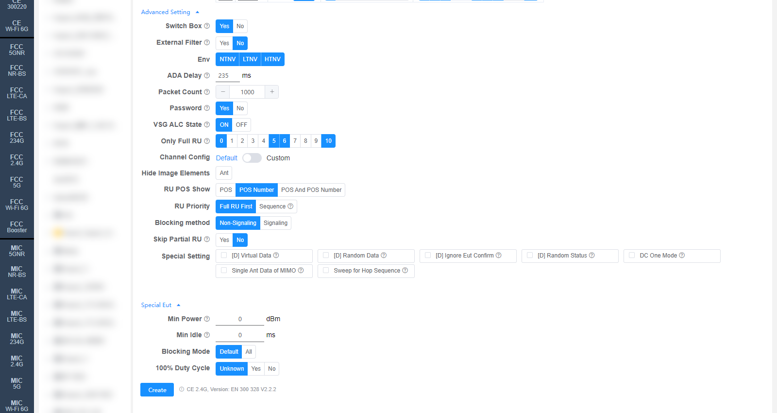
The following settings can generally be kept at their default values. Adjust them only when the test results are abnormal or there are special test requirements. Some fields are only displayed for specific Types, as noted in the descriptions.
Switch Box: Whether to use a Switch Box. This standard includes tests such as Adaptivity, which require a Switch Box (control box).
External Filter: Whether an external filter is used in the RF path during testing.
Manual Confirm (Bluetooth only): Whether a pop-up confirmation is required to confirm that the waveform has stabilized. For items tested in the frequency hopping state, the system's built-in algorithm for automatically determining waveform stability may misjudge because some chips hop very slowly, so this option is enabled by default for Bluetooth, and the test engineer assists in determining whether the waveform has stabilized.
Env: Environmental conditions to test, multi-select: NTNV / LTNV / HTNV (normal temp normal volt / low temp normal volt / high temp normal volt).
ADA Delay: Delay (ms) for the Adaptivity test. Used to simulate the latency in network communication; by artificially introducing a delay, it tests how the device handles latency in a real network. The default value can be changed on the Setting page.
Packet Count: Packet count, used for the receiver blocking test.
Password: WiFi password of the CMW500, used for the receiver blocking test.
VSG ALC State: Power ALC state of the vector signal generator (ON / OFF). Used for the Adaptivity test.
Channel Config: Channel configuration, Default or Custom (manually customized channels).
Hide Image Elements: Select the elements to hide in report images (e.g., the Ant antenna marker).
RU POS Show: How the RU position is displayed in the report: POS / POS Number / POS And POS Number.
RU Priority: RU test priority: Full RU First or Sequence (in the order RU26 → RU52 → RU106...).
Blocking method: Test method for receiver blocking: Non-Signaling or Signaling.
Special Setting: Special settings. Options prefixed with [D] are debug options and do not need to be checked for normal testing:
[D] Virtual Data / [D] Random Data / [D] Ignore Eut Confirm / [D] Random Status: Debug options.
DC One Mode: Only one duty cycle is tested per mode, e.g., 802.11b only measures the duty cycle of the LCH.
Single Ant Data of MIMO: Displays the EIRP and PSD data of each antenna for MIMO (CE 2.4G/5G/6G).
Sweep for Hop Sequence: The hopping sequence test uses the sweep method.
Min Power: Sets the minimum power (dBm); 0 means automatic.
Min Idle: Minimum idle time (ms). Used for C2401.
Blocking Mode: Receiver blocking test mode: Default (per the regulations, only the lowest-rate mode is tested, e.g., for b/g/n only the b mode is tested) / All (all modes are tested).
100% Duty Cycle: Whether the sample's duty cycle is 100% (Unknown / Yes / No); only needs to be selected when the system misjudges the duty cycle.
Corresponding software option: CE 2.4G (EN 300 328)