
Pass System Automatic Fixed-Frequency Test
Interface Overview
EUT Auto V4 uses a left navigation bar layout, with the version number and documentation link shown at the top. The navigation bar has four pages:
| Page | Function |
|---|---|
| Dashboard | Main control page: configure connection parameters and start fixed-frequency |
| Settings | Configure RF parameter presets for each chip |
| Manual Control | Manually send fixed-frequency commands for debugging and verification |
| Self-Defined | Customize fixed-frequency command templates for new chips |
Basic Operations
Step 1: After connecting the hardware devices, open EUT Auto and go to the Dashboard page
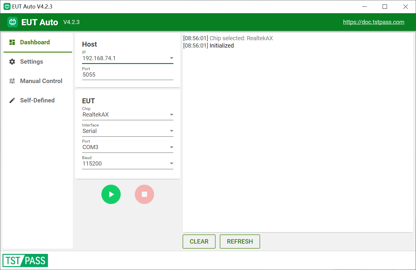
The center of the Dashboard page is divided into two card areas:
Host card (connection between EUT Auto and the TST PASS system)
- In the IP field, select the IP of the current computer (if the system has multiple IP addresses, select the one on the same subnet as the TSTPASS system, usually 10.0.0.xx)
- In the Port field, fill in the port number, default 5055 (when controlling multiple samples for automatic fixed-frequency on the same computer, fill in a different Port for each window to distinguish the samples)
EUT card (connection between EUT Auto and the sample)
- In the Vendor field select the chip manufacturer, then select the chip model in the Chip field; after selection, the interface shows usage tips for that chip (driver, pre-processing notes, etc.), and the baud rate automatically switches to the chip's default value
- In the Interface field, select the communication interface type with the sample:
- Serial: select the corresponding Port (COM port) and Baud (baud rate)
- ADB: select the corresponding ADB Device
- USB: select the corresponding USB Device
- SSH / Telnet / IPOP: fill in Server (IP address), Username and Password
- MP DLL / HQA DLL / AC DLL (DLL direct call): dedicated to MediaTek and Realtek USB adapter solutions; the software switches automatically when the corresponding chip is selected, no manual selection needed. For MediaTek HQA, leaving Host empty means local USB/PCIe/SDIO auto-detection, while filling in an IP controls an AP SoC (OpenWrt router board) via Ethernet
Start control
- Click the green ▶ button to start automatic fixed-frequency, click the pink ⬛ button to stop
- The log area on the right shows the fixed-frequency command traffic in real time; click CLEAR to clear the log, or REFRESH to refresh the available COM port/device lists
Step 2: Configure the corresponding EUT Auto Setting on the Settings page
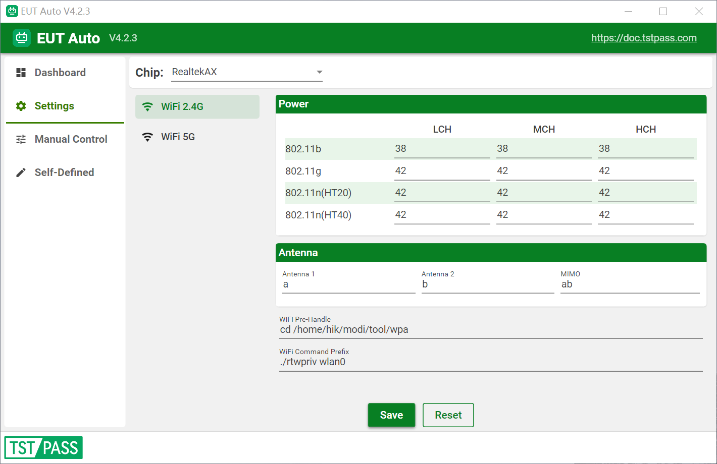
- In the Vendor and Chip drop-down boxes at the top, select the chip model to configure (this selection is linked with the Dashboard page; the chip selected on the Dashboard is automatically synced here)
- In the left sidebar, select the RF function to set; the list shows only the technologies actually supported by the chip (Wi-Fi 2.4G / Wi-Fi 5G / Wi-Fi 6G / Bluetooth / BLE)
- Set the corresponding power and other parameters according to project requirements. For Wi-Fi technologies, power can be set per modulation and bandwidth for low/middle/high channels; for Bluetooth technologies, power can be set per low/middle/high channel; leave empty (0) to use the default power
- Click the Save button to save the settings, or Reset to restore defaults
- Return to the Dashboard page and click ▶ to start fixed-frequency
Step 3: Set the corresponding EUT Auto IP in the TST PASS system
Note:
Entering the EUT Auto IP is considered as enabling automatic fixed-frequency testing, and subsequent tests can proceed normally without pop-up fixed-frequency prompts.
If subsequent tests do not require automatic fixed-frequency testing, please delete the IP here.
Support for Simultaneous Automatic Fixed-Frequency Testing of Multiple Samples
- Click EUT Auto.exe to open multiple automatic fixed-frequency windows simultaneously
- Provided the samples are correctly set up and connected, different automatic fixed-frequency windows can select the corresponding chip type
- Click the ▶ button for each window one by one to begin automatic fixed-frequency testing
Note:
- When performing automatic fixed-frequency testing on multiple samples simultaneously, different Host Ports must be set to avoid fixed-frequency conflicts.
- Some samples may require pre-configuration depending on the actual usage scenario (e.g. Airoha and BES solutions require pre-processing).
- When performing automatic fixed-frequency testing on multiple samples simultaneously, pausing or configuring one sample individually does not affect the automatic fixed-frequency testing of other samples.
- The samples supported by the automatic fixed-frequency software are continuously being updated. For details, please see Supported Samples
Manual Control
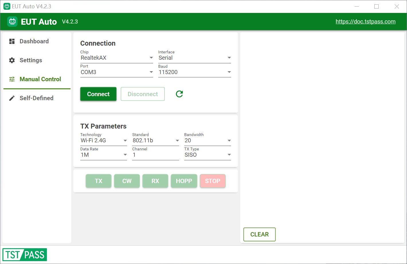
The Manual Control page allows sending fixed-frequency commands to the sample directly and manually, without connecting to the TST PASS system. It is suitable for debugging and verification.
- At the top of the page, select the chip (Vendor + Chip) and interface type (same as the Dashboard), then click Connect to connect the sample
- Select the test technology (the list shows only technologies supported by the chip), standard (e.g. 802.11b/g/n/ax), bandwidth, channel and data rate; for Wi-Fi technologies you can also choose the SISO / MIMO TX type
- Click the corresponding button to send commands directly: TX (modulated transmission), CW (carrier transmission), RX (receive), HOPP (frequency-hopping transmission), STOP (stop)
- The log area at the bottom shows the command traffic
Note: Manual Control and the Dashboard's automatic fixed-frequency are mutually exclusive; manual control cannot be used while automatic fixed-frequency is running, and vice versa.
Self-Defined (Custom Chip)
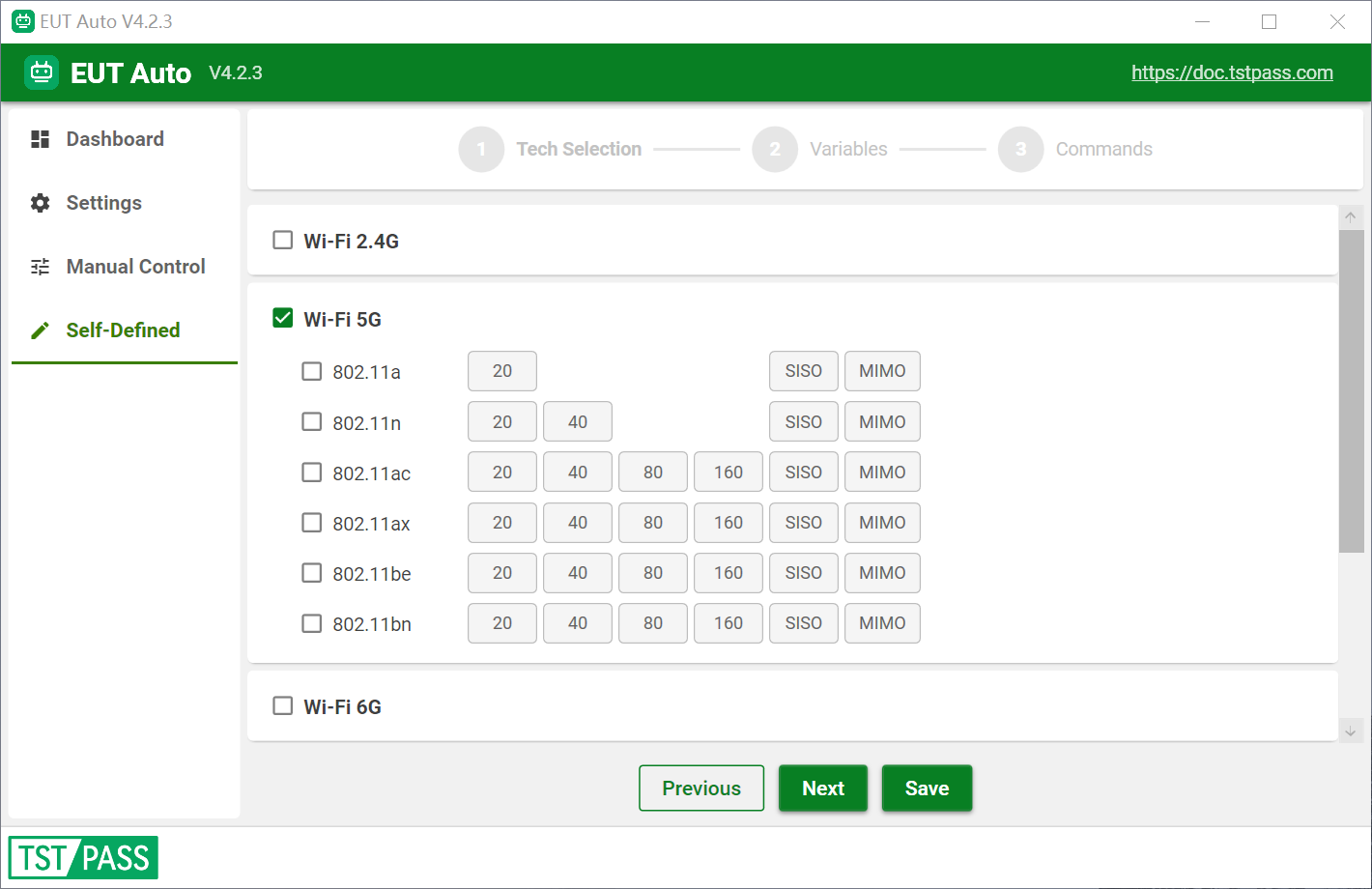
The Self-Defined page allows users to configure fixed-frequency commands for custom chips, suitable for new chip solutions not yet included in the list. The configuration is done through a three-step wizard:
- Technology and standard selection: check the technologies to support (Wi-Fi 2.4G/5G/6G, Bluetooth, BLE) and the corresponding bandwidths/packet types, and choose whether to support carrier wave transmission and the TX/RX/HOPP modes
- Variable configuration: set the antenna mapping, channel format (decimal/hexadecimal) and power values per technology-bandwidth combination
- Command templates: for each technology combination, fill in the actual commands sent to the chip, using
{ch},{ant},{bw},{power}as placeholders; separate multiple commands with;|
⚠️ Note: The Self-Defined feature is still under debugging and is not recommended for formal testing yet.