
Creating a Test Plan - FCC 5G
The FCC 5G option is used for North American FCC / IC (ISED) certification testing of products in the 5 GHz U-NII bands. When creating a test plan, select the Type (technology) first: UNII / Proprietary. Each type is described separately below.
UNII
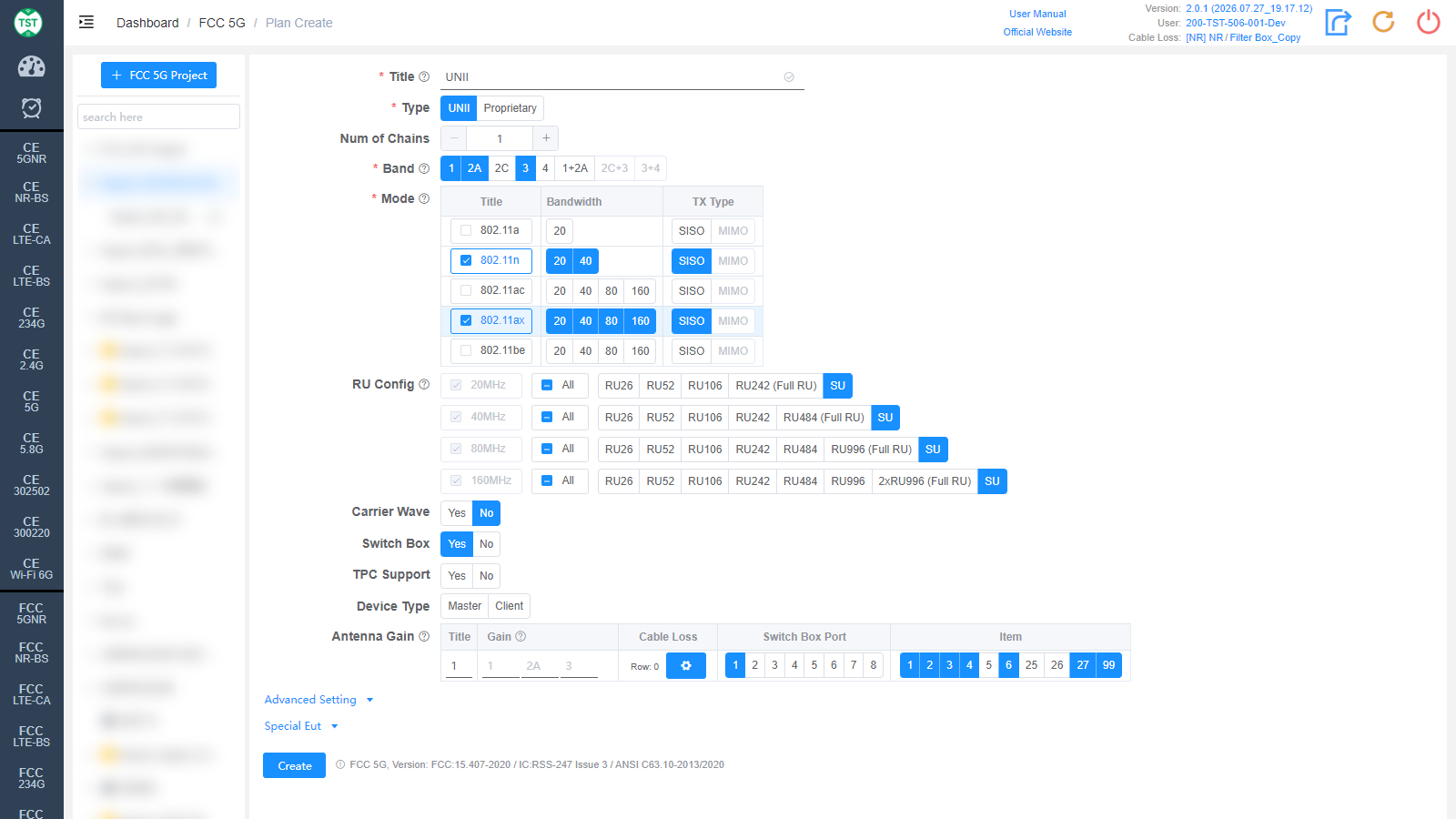
Title: Test plan name, entered by the user, e.g., UNII / WiFi-5G.
Type: Technical category, select UNII here.
Num of Chains: Number of transmit chains (antennas) the product has.
Band: Operating bands supported by the product (required), multi-select: 1 / 2A / 2C / 3 / 4 and the cross-band combinations 1+2A / 2C+3 / 3+4 (corresponding to U-NII-1 / 2A / 2C / 3 / 4). Band 1+2A refers to the entire 5150 ~ 5350 MHz range: if the product supports 160MHz bandwidth, the channel at 5250MHz spans both Band 1 and 2A; if the product does not support 160MHz bandwidth, Band 1+2A does not need to be selected. Band 2C+3 is mainly for the three Cross Band CHs CH144 / 142 / 138 (5720 / 5710 / 5690); if the product supports these three Channels, this Band needs to be selected.
Mode: Modes supported by the product (required): 802.11a / n / ac / ax / be. After checking a mode, select the corresponding Bandwidth (20 / 40 / 80 / 160 MHz) and TX Type (SISO / MIMO). Displayed after a Band is selected.
RU Config: RU (Resource Unit) configurations supported by 802.11ax / be devices. The Full RU of each bandwidth is required; select the other RU configurations according to the product's actual support. Displayed after 802.11ax / be is checked.
Carrier Wave: Whether the product supports carrier wave transmission. If Yes is selected, the frequency error will be measured in carrier wave mode; the test setup differs considerably from the modulated signal test.
Switch Box: Whether to use a Switch Box. If a Switch Box has not been purchased, select No, and the product will be directly connected to the spectrum analyzer for testing.
TPC Support: Confirm whether the product supports TPC (Transmit Power Control, a mechanism that can automatically adjust the product's transmit power). This option affects the Power and PSD Limits. Displayed after a DFS band (Band 2A / 2C / 3) is selected.
Device Type: DFS device type of the product: Master (master device, which actively performs radar listening) / Client (client device). Displayed after a DFS band is selected.
Antenna Gain:
Title: Antenna number, named sequentially by default as 1, 2, 3, 4..., or manually input other names according to customer requirements.
Gain: Gain of each antenna in the corresponding band (Band).
Cable Loss: Cable loss of the RF cable from the product's antenna port to the Switch Box (RF port of the switch) or the SA (spectrum analyzer). How to Create Common Cable Loss.
Switch Box Port: Port number of the switch connected to the product's antenna.
Item: Test items for each antenna; the numbers correspond as follows:
(F5001) Duty Cycle
(F5002) Bandwidth
(F5003) Maximum Conducted Output Power
(F5004) Maximum Power Spectral Density
(F5005) Unwanted Emissions In Restricted Frequency Bands
(F5006) Frequency Stability
(F5025) Band Edge
(F5026) Spurious Emission
(F5027) Additional Spurious Emission
(F5099) Form731 — FCC Form 731 report
The software preselects the default test items according to the technical characteristics. Note: In some cases, test parameters are mutually referenced between items; it is recommended to create the test plan with the default items.
Proprietary
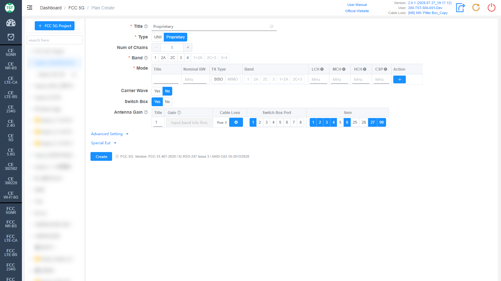
Type: Technical category, Proprietary (custom product).
Band: Same as UNII.
Mode: Custom mode table:
Title: Mode number; other names can be manually input according to customer requirements.
Nominal BW: Sets the nominal bandwidth occupied by the signal on the spectrum.
TX Type: Transmission type, SISO / MIMO.
LCH / MCH / HCH: Low / middle / high channel frequency settings (MHz).
CSP: Channel Spacing.
Action: Used to add / delete mode configuration rows.
Carrier Wave / Switch Box / Antenna Gain are the same as UNII and are not repeated here.
Advanced Setting and Special Eut Settings
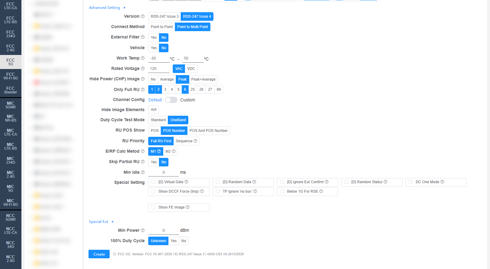
The following settings can generally be kept at their default values. Adjust them only when the test results are abnormal or there are special test requirements.
Version: Canada IC regulation version: RSS-247 Issue 3 / RSS-247 Issue 4. The default value can be changed on the Setting page.
Connect Method: Confirm whether the product is a P2P (Point to Point) or P2MP (Point to Multi Point) product, default P2MP. Most common products are P2MP, such as home routers and phones. If the Antenna Gain exceeds 6 dB, this option affects the calculation of the conducted power limit reduction. For details, refer to FCC Part 15.407(a)(1)(iii) and 15.407(a)(3) eCFR Part 15E
External Filter: Whether an external filter is used in the RF path during testing.
Vehicle: Confirm whether the product is a vehicle-mounted product, default No. For Band 1, the Canada IC Limit for vehicle-mounted products differs from that for other products; for details, refer to RSS-247 Section 6.2.1.1 RSS-247
Work Temp: Operating temperature range (°C) of the product. Affects the frequency stability test.
Rated Voltage: Rated operating voltage (VAC / VDC) of the product. Affects the frequency stability test.
Hide Power (CHP) Image: Option to hide the CHP power images in the report: No / Average / Peak / Peak+Average, applicable to the F5003 report.
Only Full RU: The checked items test only the Full RU. Displayed after 802.11ax / be is checked.
Channel Config: Channel configuration, Default or Custom (manually customized channels).
Hide Image Elements: Select the elements to hide in report images (e.g., the Ant antenna marker).
Duty Cycle Test Mode: Duty cycle test mode: Standard / OneBand (single channel).
RU POS Show: How the RU position is displayed in the report: POS / POS Number / POS And POS Number.
RU Priority: RU test priority: Full RU First or Sequence (in the order RU26 → RU52 → RU106...).
EIRP Calc Metod: EIRP calculation method for MIMO:
M1: EIRP (MIMO) = EIRP_ANT1 + EIRP_ANT2 (converted to mW for summation, then converted back to dBm).
M2: EIRP (MIMO) = Conducted Power_MIMO + Directional Gain.
Skip Partial RU: Whether to skip the Partial RU test. Displayed after 802.11ax / be is checked.
Min Idle: Minimum idle time (ms) for the duty cycle test.
Special Setting: Special settings. Options prefixed with [D] are debug options and do not need to be checked for normal testing:
[D] Virtual Data / [D] Random Data / [D] Ignore Eut Confirm / [D] Random Status: Debug options.
DC One Mode: Only one duty cycle is tested per mode.
Show DCCF Force (tmp): Temporary option to force the DCCF to be displayed in the F5003 / F5004 images.
TP ignore 'no box': Test Priority ignores the "no switch box" scenario. By default, in the no-switch-box scenario, fixed-frequency antennas have the lowest priority.
Below 1G For RSE: When checked, the RSE test will include frequencies below 1 GHz.
Show FE Image: When checked, the frequency error images are displayed (all displayed by default).
Min Power: Sets the minimum power (dBm); 0 means automatic.
100% Duty Cycle: Whether the sample's duty cycle is 100% (Unknown / Yes / No); only needs to be selected when the system misjudges the duty cycle.
Corresponding software option: FCC 5G (FCC Part 15.407 / IC RSS-247)