Creating a Test Plan - MIC 2.4G
The MIC 2.4G option is used for Japan MIC (総務省) technical conformity certification testing of unlicensed products in the 2.4 GHz band. When creating a test plan, select the Type (technology) first: WLAN / Bluetooth / BLE / Zigbee / Proprietary. Each type is described separately below.
WLAN
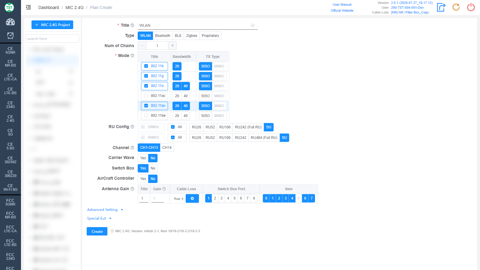
Title: Test plan name, entered by the user, e.g., WLAN / BT / WiFi-Ant1.
Type: Technical category, select WLAN here.
Num of Chains: Number of transmit chains (antennas) the product has.
Mode: Modes supported by the product (required): 802.11b / g / n / ac / ax / be. After checking a mode, select the corresponding Bandwidth (20 / 40 MHz) and TX Type (SISO / MIMO).
RU Config: RU (Resource Unit) configurations supported by 802.11ax / be devices. The Full RU of each bandwidth is required; select the other RU configurations according to the product's actual support. Displayed after 802.11ax / be is checked.
Channel: CH1-CH13 are tested by default; if the product also supports CH14 (802.11b dedicated channel), simply select CH14 as well.
Carrier Wave: Whether the product supports carrier wave transmission. If Yes is selected, the frequency error will be measured in carrier wave mode; the test setup differs considerably from the modulated signal test.
Switch Box: Whether to use a Switch Box. If a Switch Box has not been purchased, select No, and the product will be directly connected to the spectrum analyzer for testing.
AirCraft Controller: Confirm whether the product is a drone remote controller, default No.
Antenna Gain:
Title: Antenna number, named sequentially by default as 1, 2, 3, 4..., or manually input other names according to customer requirements.
Gain: Gain of each antenna in the corresponding band (Band).
Cable Loss: Cable loss of the RF cable from the product's antenna port to the Switch Box (RF port of the switch) or the SA (spectrum analyzer). How to Create Common Cable Loss.
Switch Box Port: Port number of the switch connected to the product's antenna, e.g., Ant1 connected to port 1, Ant2 connected to port 2.
Item: Test items for each antenna; the numbers correspond as follows:
(M2400) Duty Cycle
(M2401) Frequency Error (周波数の許容偏差)
(M2402) Occupied Bandwidth (占有周波数帯幅)
(M2403) Spread Bandwidth
(M2404) Antenna Power (空中線電力)
(M2405) Dwell Time
(M2406) Spurious Emission Intensity
(M2407) Secondary Radiated Emission
The software preselects the default test items according to the characteristics of each technology. Note: In some cases, test parameters are mutually referenced between items; it is recommended to create the test plan with the default items.
Bluetooth
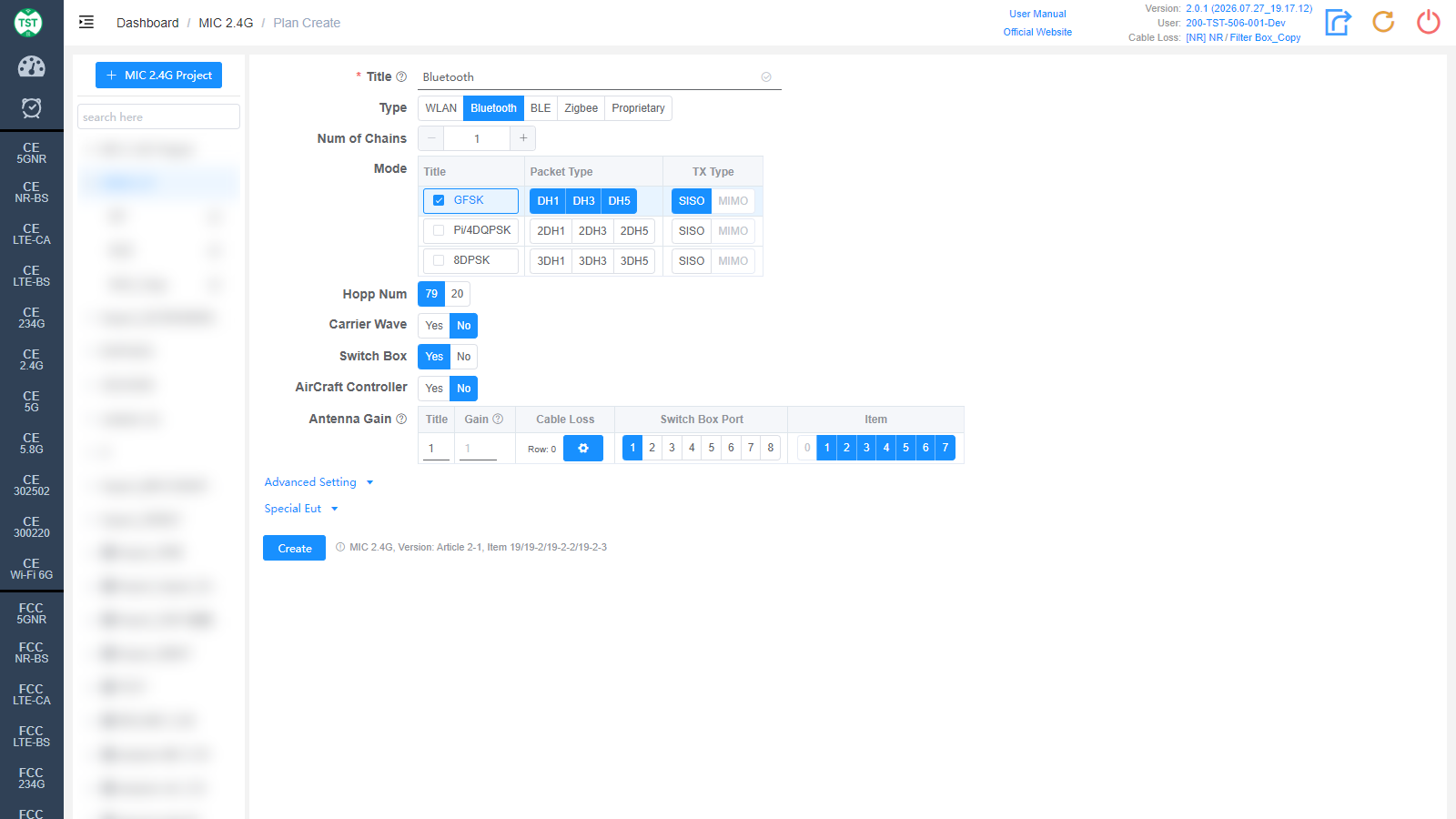
Type: Technical category, select Bluetooth here.
Num of Chains: Number of transmit chains the product has; Bluetooth currently supports only a single antenna.
Mode: Modulations and packet types (Packet Type) supported by the product: GFSK (DH1/DH3/DH5), Pi/4DQPSK (2DH1/2DH3/2DH5), 8DPSK (3DH1/3DH3/3DH5).
Hopp Num: Bluetooth tests 79 channels by default. Some Japanese review bodies require the power measurement results in the 20-channel state to be additionally provided for the power test; if this is required, simply select both the 79 and 20 channels.
Carrier Wave / Switch Box / AirCraft Controller / Antenna Gain are the same as WLAN and are not repeated here.
BLE
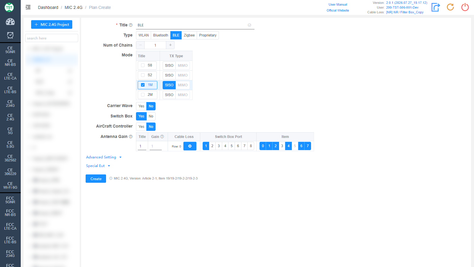
Type: Technical category, select BLE here.
Num of Chains: Number of transmit chains the product has; BLE currently supports only a single antenna.
Mode: Modes supported by the product: S8 / S2 / 1M / 2M. S8 and S2 are Long Range rates introduced in BT 5.0 (based on 1M + FEC forward error correction); their test results are basically identical to 1M. For products that support all three rates, generally only the 1M mode is tested.
Carrier Wave / Switch Box / AirCraft Controller / Antenna Gain are the same as WLAN and are not repeated here.
Zigbee
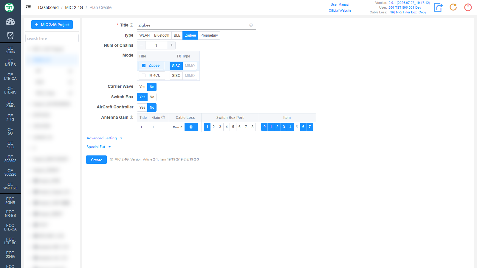
Type: Technical category, select Zigbee here.
Num of Chains: Number of transmit chains (antennas) the product has.
Mode: Modes supported by the product: Zigbee / RF4CE.
Carrier Wave / Switch Box / AirCraft Controller / Antenna Gain are the same as WLAN and are not repeated here.
Proprietary
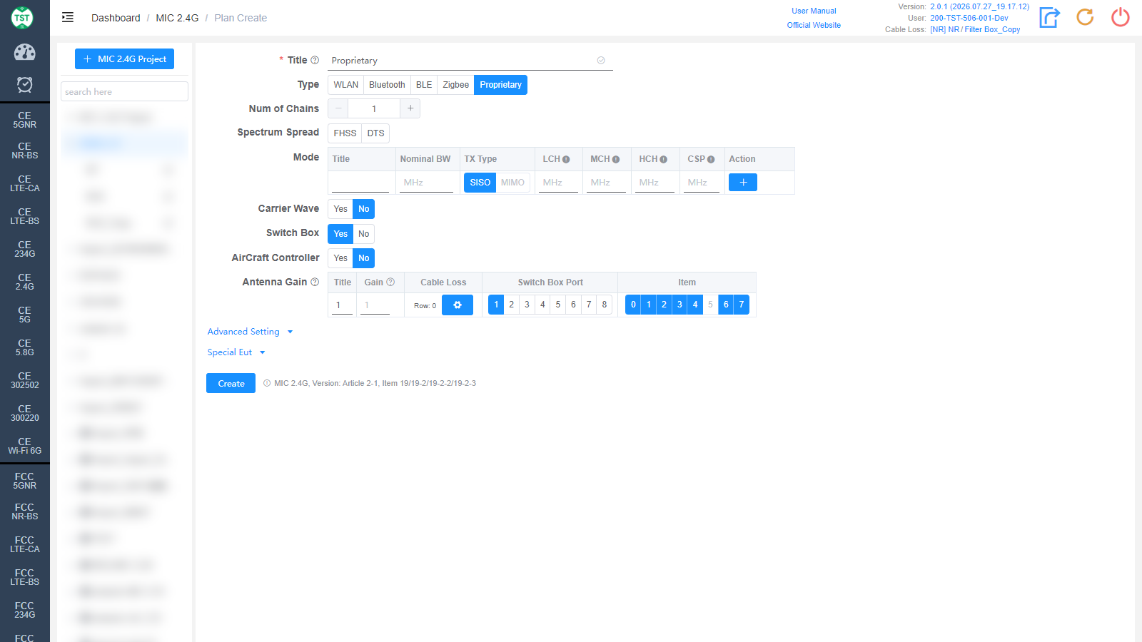
Type: Technical category, Proprietary (custom product).
Num of Chains: Number of transmit chains (antennas) the product has.
Mode: Custom mode table:
Title: Mode number; other names can be manually input according to customer requirements.
Nominal BW: Sets the nominal bandwidth occupied by the signal on the spectrum.
TX Type: Transmission type, SISO / MIMO.
LCH / MCH / HCH: Low / middle / high channel frequency settings (MHz).
CSP: Channel Spacing.
Action: Used to add / delete mode configuration rows.
Carrier Wave / Switch Box / AirCraft Controller / Antenna Gain are the same as WLAN and are not repeated here.
Advanced Setting and Special Eut Settings
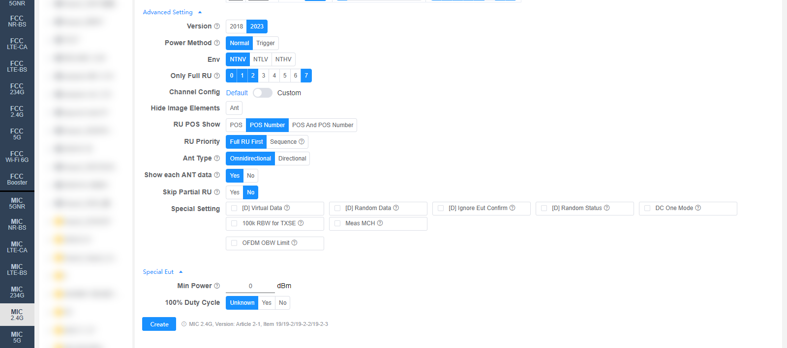
The following settings can generally be kept at their default values. Adjust them only when the test results are abnormal or there are special test requirements. Some fields are only displayed for specific Types, as noted in the descriptions.
Version: Regulation version used for testing, selectable 2018 / 2023. The default value can be changed on the Setting page.
Manual Confirm (Bluetooth only): Whether a pop-up confirmation is required to confirm that the waveform has stabilized. For items tested in the frequency hopping state, some chips hop very slowly, which may cause the automatic determination to misjudge; this option is enabled by default for Bluetooth, and the test engineer assists in the determination.
Power Method: Power measurement method: Normal / Trigger.
Env: Environmental conditions to test, multi-select: NTNV / NTLV / NTHV (normal / low / high voltage at normal temperature).
Channel Config: Channel configuration, Default or Custom (manually customized channels).
Hide Image Elements: Select the elements to hide in report images (e.g., the Ant antenna marker).
RU POS Show: How the RU position is displayed in the report: POS / POS Number / POS And POS Number.
RU Priority: RU test priority: Full RU First or Sequence (in the order RU26 → RU52 → RU106...).
Ant Type: Antenna type: Omnidirectional / Directional.
Show each ANT data: Whether to display the data of each antenna for MIMO. Used for spurious emissions and out-of-band emissions.
Special Setting: Special settings. Options prefixed with [D] are debug options and do not need to be checked for normal testing:
[D] Virtual Data / [D] Random Data / [D] Ignore Eut Confirm / [D] Random Status: Debug options.
DC One Mode: Only one duty cycle is tested per mode.
100k RBW for TXSE: Transmitter spurious emissions (30 MHz ~ 1000 MHz) use 100 kHz RBW. Modifying this option requires a retest to take effect.
Meas MCH: Whether to measure the middle channel (MCH).
OFDM OBW Limit: Occupied bandwidth limit option for OFDM modes.
Min Power: Sets the minimum power (dBm); 0 means automatic.
100% Duty Cycle: Whether the sample's duty cycle is 100% (Unknown / Yes / No); only needs to be selected when the system misjudges the duty cycle.
Corresponding software option: MIC 2.4G