
Adaptivity Test Standard Operating Procedure
Scope: Adaptive equipment operating in the 2.4 GHz and 5 GHz bands
Reference standards: EN 300 328 (2.4 GHz, adaptivity / channel access mechanism); EN 301 893 (5 GHz, §4.2.7 Adaptivity, including the Idle Period probability evaluation)
Corresponding TSTPASS test items: C2405 (CE 2.4G) / C5008 (CE 5G) / C6008 (CE WiFi 6G) / S2408 (SRRC)
1. Test Purpose
To ensure efficient use of the spectrum and reduce mutual interference between different devices in the same environment, the regulations impose Adaptivity requirements (i.e., the Channel Access Mechanism) on Adaptive equipment.
The purpose of the test is to evaluate whether, when another signal (interference) appears on the channel, the device can detect that the channel is occupied as required by the regulations, stop transmitting and back off, and resume transmission once the channel becomes idle — that is, to verify the effectiveness of the device's Listen Before Talk (LBT) mechanism.
2. Test Principle
The test system uses a signal generator to apply an interference signal on the EUT's operating channel, simulating a scenario in which the channel is occupied by another device; throughout the test, the EUT maintains full-load data transmission via traffic generation software. The spectrum analyzer observes the interference signal and the EUT signal simultaneously:
- While the interference is applied: the EUT should detect that the channel is occupied and stop transmitting
- After the interference is removed: the EUT should resume transmission within the time allowed by the regulations
The system automatically controls the timing of applying and removing the interference signal according to the regulatory requirements, records the EUT's transmission stop / resume behavior, and makes the judgment.
Related Configuration
The behavior of the Adaptivity test is directly related to the following product characteristic settings in the test plan; for the meaning of each option, see the plan creation documents of the corresponding standards:
- Frame Type (FBE / LBE), CAM Option (Test / Declaration), Priority Class (1 ~ 4), Initiating / Responding, Supervising / Supervised — see the CE 5G and CE WiFi 6G plan creation documents
- ADA Delay and VSG ALC State in the Advanced Setting also affect this test
3. Test System Composition and Connection
Required equipment: EUT sample / spectrum analyzer (SA) / signal generator (VSG or ASG) / receiving device (paired device) / TSTPASS system
Test software: TSTPASS system; traffic generation software (e.g., EspRFTestTool, iperf3; EspRFTestTool is used in the examples below)
Connection
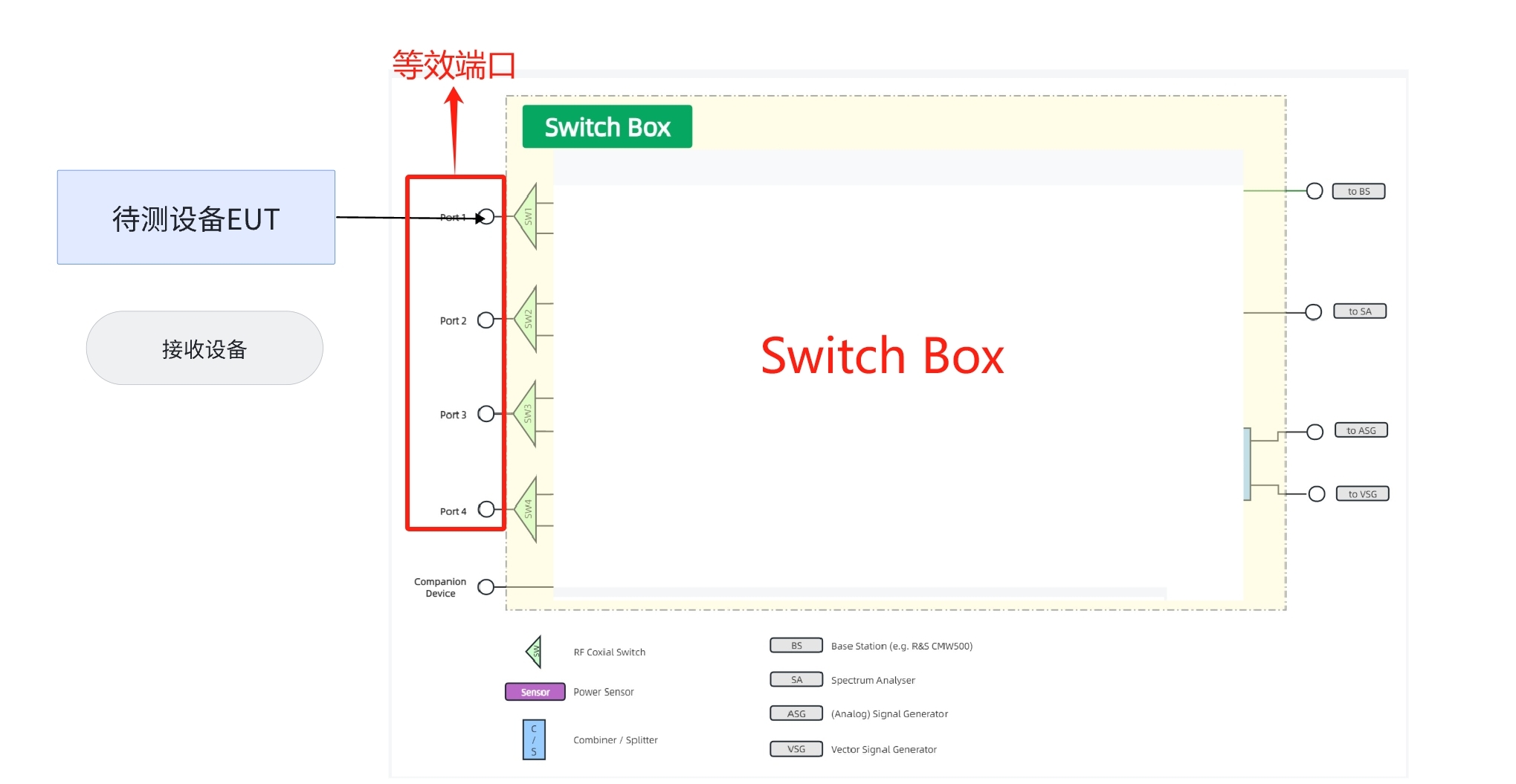
Complete the RF cable connections on the rack: the test ports (1 ~ 4) on the front panel of the rack are equivalent; connect the ASG / VSG / SA to the corresponding ports on the rear of the rack. Connect the sample under test, acting as the client, to a front-panel port of the rack and power it on; connect the receiving device, acting as the server, to the computer via a wired / wireless connection. The connection is illustrated below:
4. TSTPASS Test Procedure
Step 1: Create a Test Plan
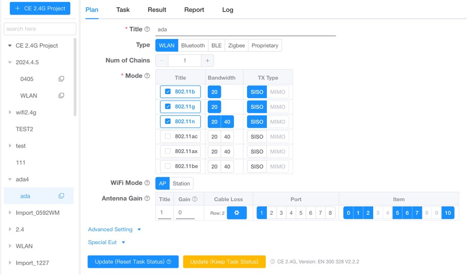
Select the corresponding standard (e.g., CE 2.4G / CE 5G) in the TSTPASS system and create a test plan according to the product characteristics (example below):
Step 2: Select the Test Item
On the Task page, check the Adaptivity (Channel Access Mechanism) test item and start the test.
Step 3: Set the Sample State per the System Pop-up
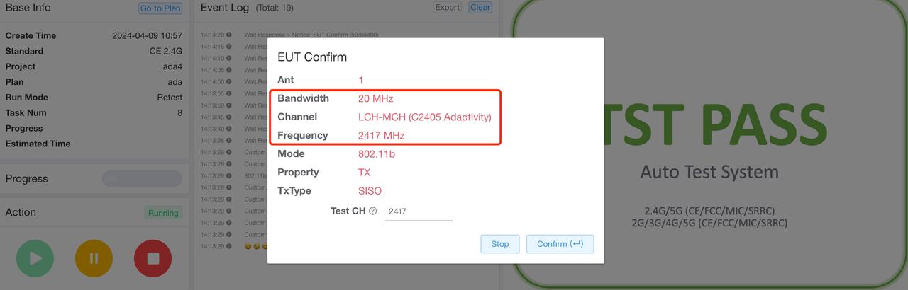
Following the information in the system task pop-up (shown below), set the sample to the specified channel and bandwidth in the router's management page (or the sample's control interface), and observe the signal change on the SA to confirm that the setting has taken effect:
Step 4: Start Traffic
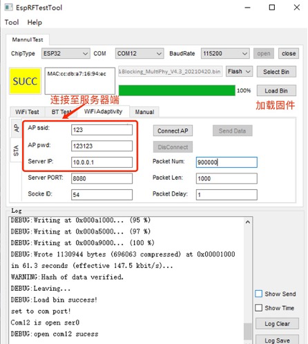
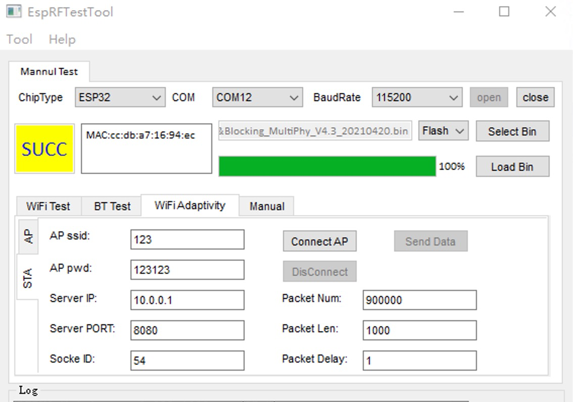
Use the traffic generation software to keep the sample under test transmitting packets continuously. Taking EspRFTestTool as an example, for a sample working in Station mode: open the WiFi Adaptivity page, click STA on the left, enter the name and password of the laboratory AP to complete the connection, set the parameters as shown in the figure below, and then click Send Data to start the traffic:
Step 5: Complete All Channel / Bandwidth Combinations
Following the system pop-up prompts, change the channel and bandwidth of the sample under test one combination at a time and repeat the test until all combinations are completed; the system records the data and makes the judgment automatically.
Ways to change the sample's channel: log in to the sample's control interface and change it directly, or change the channel/bandwidth of the master device (AP) so that the slave device switches accordingly.
5. Traffic Generation Methods
The Adaptivity test requires the EUT to maintain full-load transmission during the test (to meet the regulatory duty cycle requirement). Two traffic generation methods are commonly used:
Method 1: iperf3
- Server side: run
iperf3 -sto start server mode; detailed reports on bandwidth, jitter, packet loss, etc. are available - Client side: run
iperf3 -c <server IP address> -b 20M -t <test duration>to send data to the server continuously
Method 2: EspRFTestTool (ESP series products)
After downloading the bin, set the baud rate of EspRFTestTool to 115200.
- Station mode sample: click WiFi Adaptivity → STA on the left → enter the name and password of the laboratory AP → click Connect AP; the status bar shows the connection log. After the connection succeeds, change packet num to 900000 (convenient for long-duration traffic), change packet delay to 1, select the socket ID corresponding to the chip, and click Send Data:
- AP mode sample: click WiFi Adaptivity → AP on the left → enter the name, password, channel, and mode of the sample AP → click create, and let the laboratory STA connect to the newly created AP. After the connection succeeds, the traffic settings are the same as in Station mode.
6. FAQ
Q1: The EUT signal displayed on the spectrum analyzer is too weak. How do I troubleshoot?
First check that the hardware connections are correct and that no cable is damaged; then check whether the signal transmitted by the signal generator (ASG) is too weak — the output level of the generator can be increased appropriately.
Q2: The system reports "Duty Cycle not satisfied with requirement". What should I do?
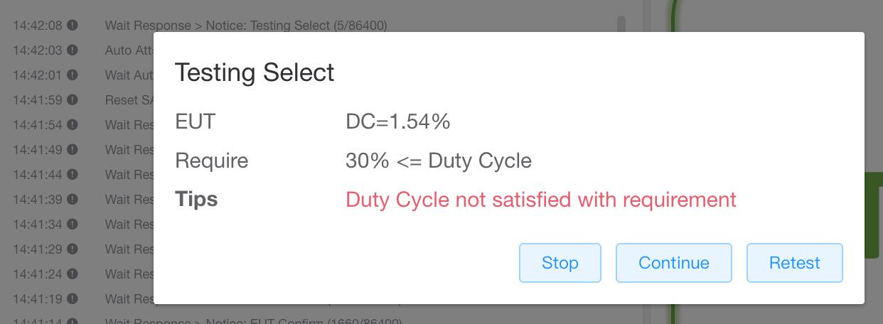
This message indicates that the EUT's transmit duty cycle has not reached the level required by the regulations. Check that Send Data has been clicked in the traffic generation software and that packets are being sent successfully; confirm that the sample is transmitting continuously at full load, then retry.
Q3: The sample disconnects or does not resume transmission during the test?
Confirm that the paired link is stable (AP signal strength, correct password). Some samples actively switch channels under strong interference; in that case, fix the sample back to the test channel as instructed by the system pop-up.