Contention Based Protocol (CBP) Test Standard Operating Procedure
Scope: Devices operating in the 6 GHz U-NII-5 ~ U-NII-8 (5.925 ~ 7.125 GHz) bands
Reference standard: FCC KDB 987594 D02 Section I (Contention Based Protocol)
Corresponding TSTPASS test item: F6008 (FCC WiFi 6G)
1. Test Purpose
When multiple devices share a wireless channel, collisions and contention are likely to occur. CBP (Contention Based Protocol) requires a device to yield promptly when it detects that the channel is occupied by another signal, so as to maximize spectrum efficiency.
Through the CBP mechanism, channel resources can be dynamically allocated among different devices, each device's transmission needs are handled fairly, and the probability of data collisions is reduced. The purpose of this test is to verify that the CBP function of a 6 GHz device is effective — that is, whether the device can detect an interference signal on the channel and stop transmitting.
2. Test Principle
During the test, a vector signal generator (VSG) transmits a 10 MHz wide AWGN (Additive White Gaussian Noise) signal to simulate an incumbent interference signal on the channel; the EUT maintains full-load transmission via traffic generation software; the spectrum analyzer observes the signal transmitted by the EUT to confirm whether the EUT stops transmitting after the AWGN signal appears.
Regulatory requirements on the applied level and the verification method (KDB 987594 D02 excerpt):
Using an AWGN signal generator, generate (but do not transmit, i.e., RF OFF) a 10 MHz wide AWGN signal. Set the AWGN signal power to a very low level (more than 20 dB below the -62 dBm threshold). Then, at the appropriate time, transmit the AWGN signal (RF ON) and monitor the signal analyzer to verify that the AWGN signal has been detected and that the EUT has ceased transmission.
Definition of Level (Minimal / OFF / ON)
During the test, three key levels must be determined by adjusting the VSG level and observing the spectrum (definitions from the KDB original text):
- OFF = AWGN level at which no transmission is detected, consistently for a minimum period of 10 seconds
- Minimal = AWGN level at which the system begins to trigger the transmission switch-off, albeit not being kept off consistently
- ON = AWGN level at which no impact on the transmission is detected, consistently for a minimum period of 10 seconds
| Level | Meaning |
|---|---|
| Level (OFF) | At this AWGN level, the EUT stops transmitting completely for at least 10 seconds |
| Level (Minimal) | The minimum AWGN level at which the EUT begins to trigger the transmission switch-off (but the switch-off is not yet consistently maintained) |
| Level (ON) | At this AWGN level, the EUT's transmission is completely unaffected for at least 10 seconds |
Together, these three levels characterize the device's detection threshold behavior for interference signals and are the core data for evaluating the CBP function.
3. Hardware and Software Requirements
3.1 Hardware
| Equipment | Requirement |
|---|---|
| Spectrum analyzer (SA) | Frequency range > 7.125 GHz; number of sweep points > 30000 |
| Vector signal generator (VSG) | Frequency coverage up to 7.5 GHz; or a VSG up to 6 GHz plus a Frequency Extender. Signal level dynamic range: L_min ≤ -90 dBm, L_max ≥ 0 dBm |
3.2 Software
| Software | Purpose |
|---|---|
| TSTPASS system | Test execution and data processing |
| Traffic generation software (required) | e.g., iperf, EspRFTestTool; keeps the EUT transmitting at full load |
| Device control software (if needed) | e.g., scrcpy, for convenient remote control of the sample |
iperf is used in all of the examples below.
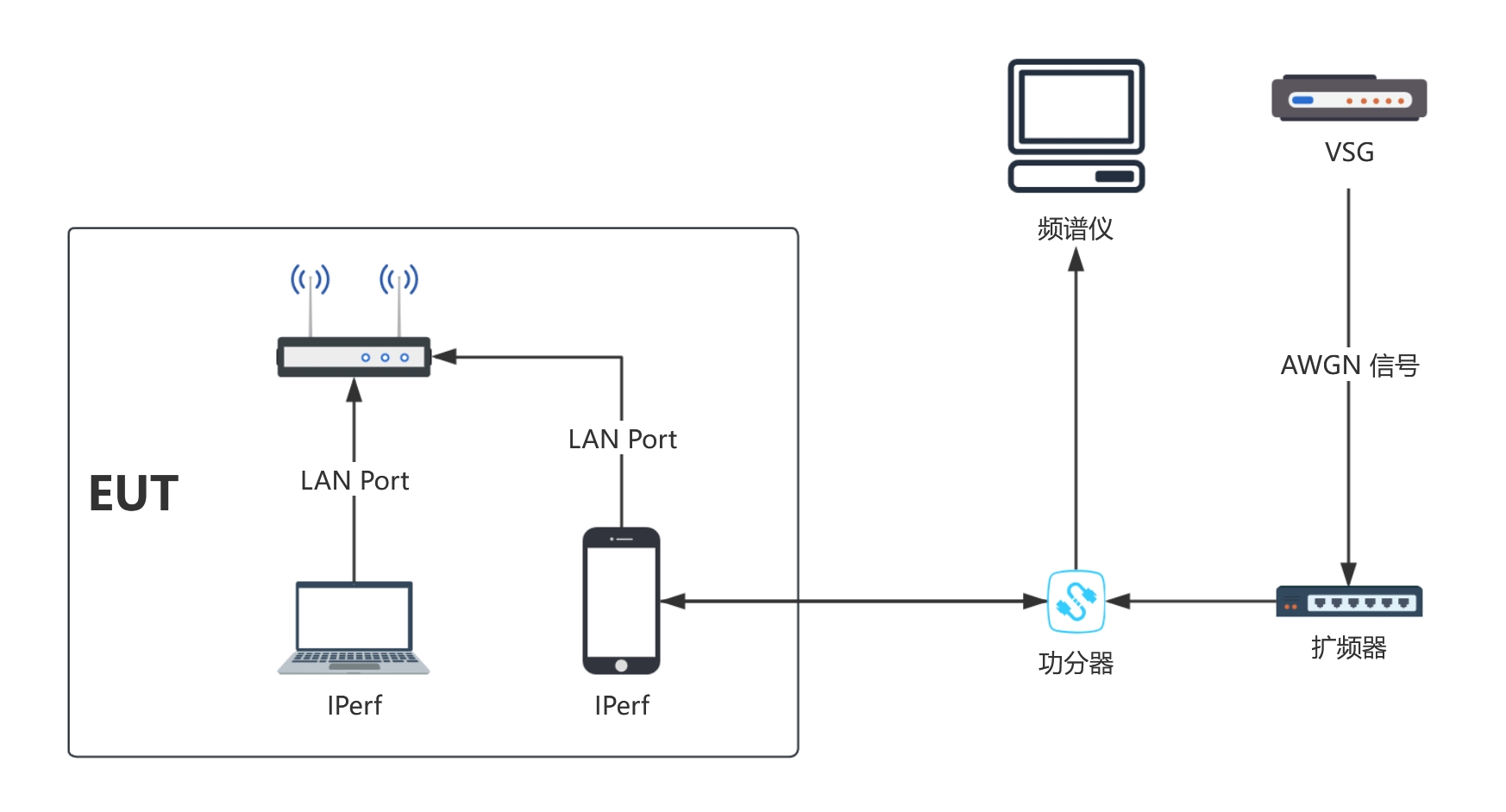
4. System Connection
- Complete the RF cable connections on the rack: connect the ASG / VSG / SA to the rear of the rack; connect the sample under test, acting as the client, to the frequency extender, then through a signal splitter to the signal analyzer and the monitoring signal analyzer, and power on the sample
- Connect the receiving device, acting as the server, to the computer via a wired / wireless connection
5. TSTPASS Test Procedure
5.1 Preparation Before the Test
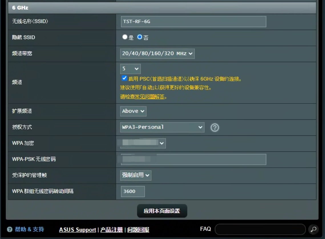
Configure the router (paired AP): set the operating channel and bandwidth
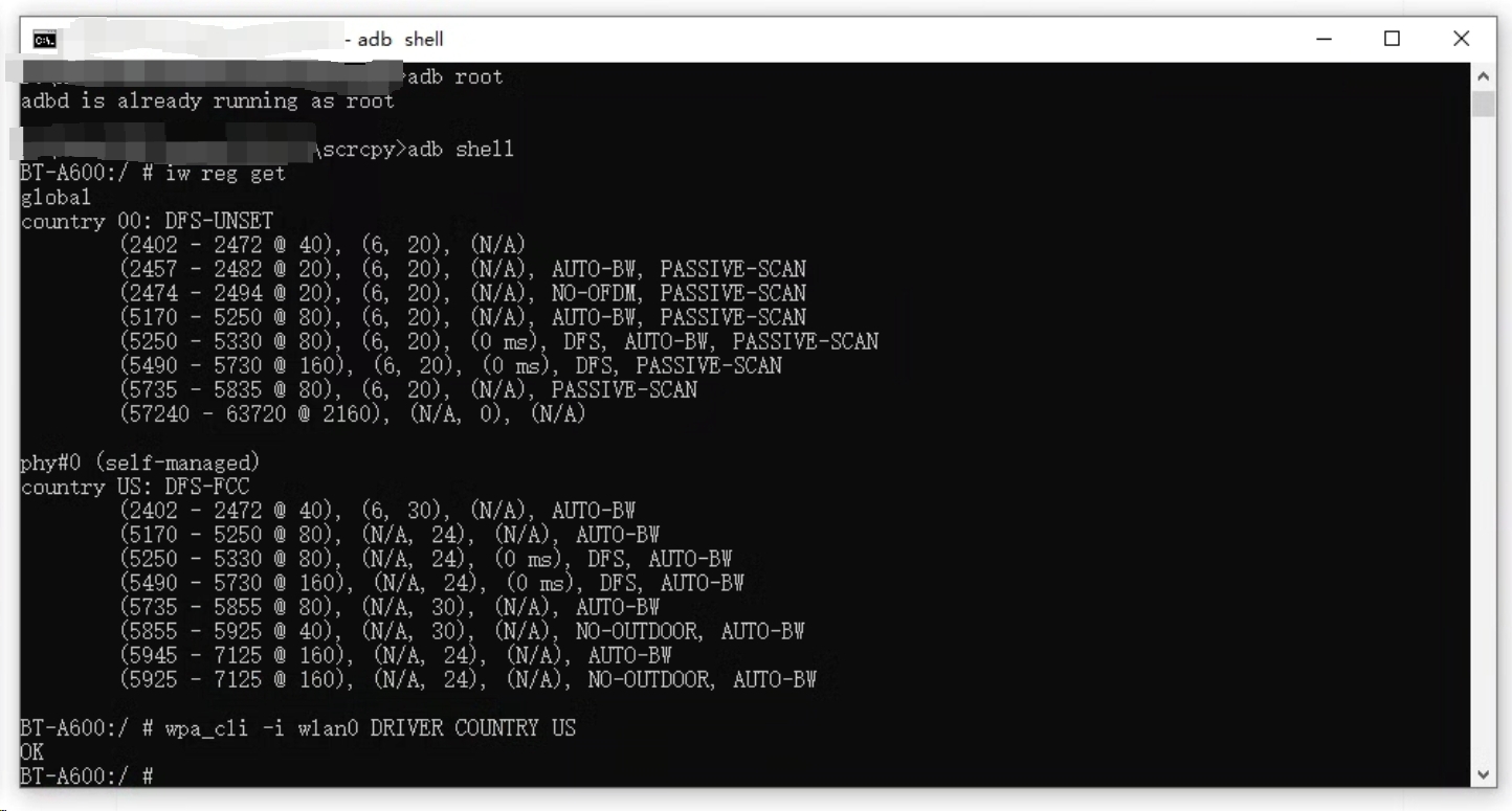
Connect the device control software (if needed):
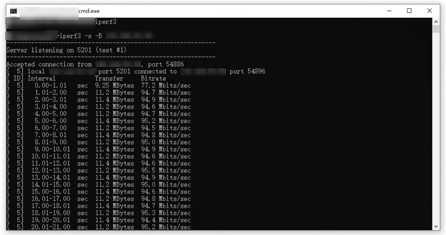
Connect the traffic generation software (iperf in this example):
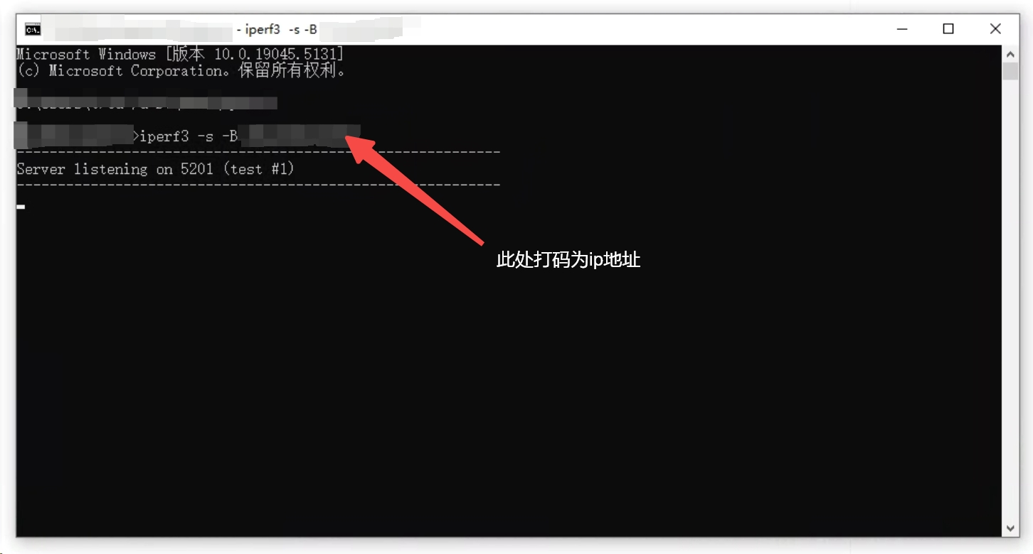
Start iperf on the sample and confirm the traffic is running:
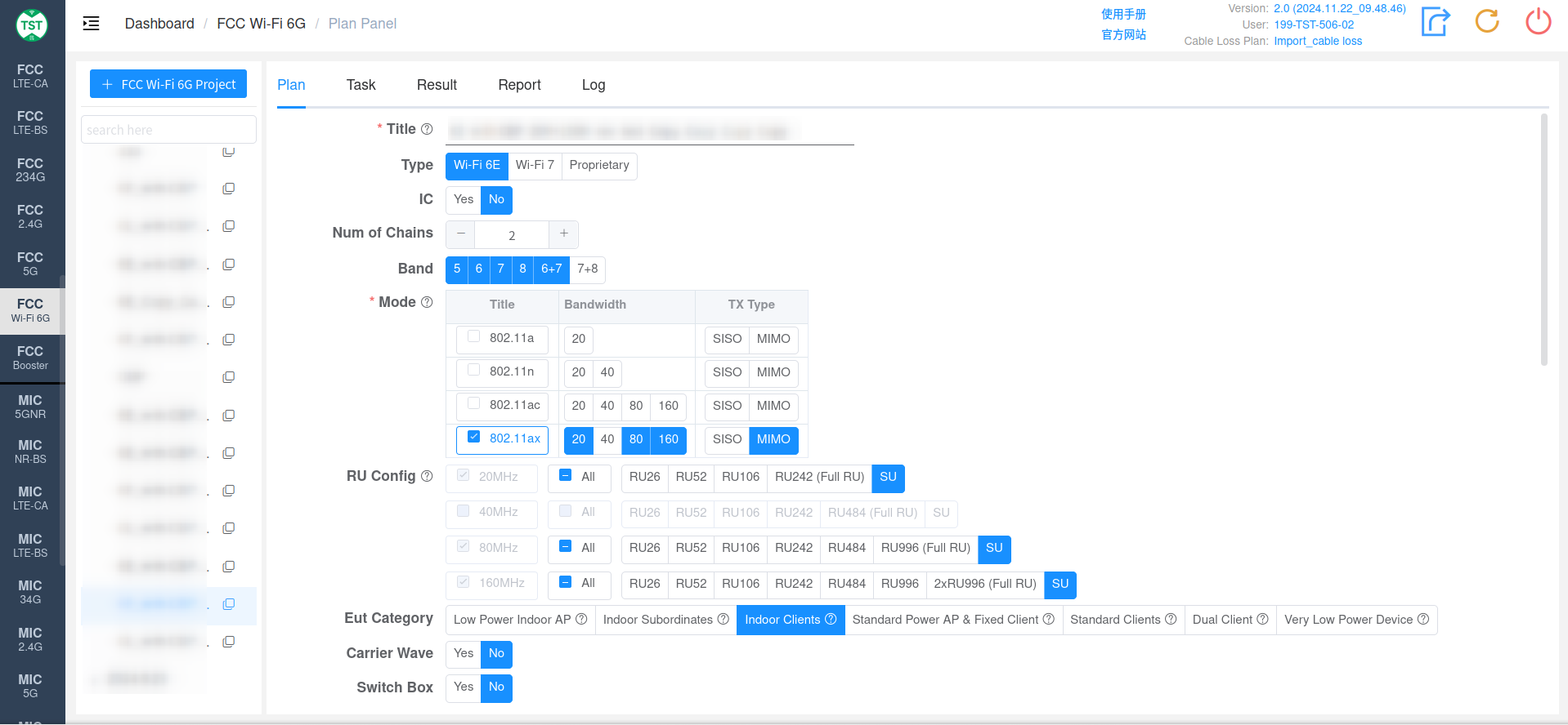
5.2 Create a Test Plan
Select the FCC WiFi 6G standard in TSTPASS, create a test plan according to the product characteristics, and check the (F6008) Contention Based Protocol test item:
5.3 Test Execution
Step 1: Test the Duty Cycle
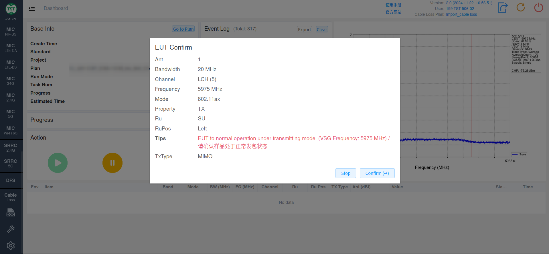
- Following the system pop-up, set the EUT operating channel (if the EUT is a client device, set the operating channel through the AP)
- Establish a normal connection between the EUT and the paired device
- Run the traffic generation software (e.g., iperf3) so that the EUT is transmitting packets normally
- Click confirm in the system to start the test
Step 2: Set the Level (Minimal) / Level (OFF) / Level (ON) Thresholds
Following the system prompts, determine the three thresholds one by one by adjusting the VSG level and observing the spectrum changes:
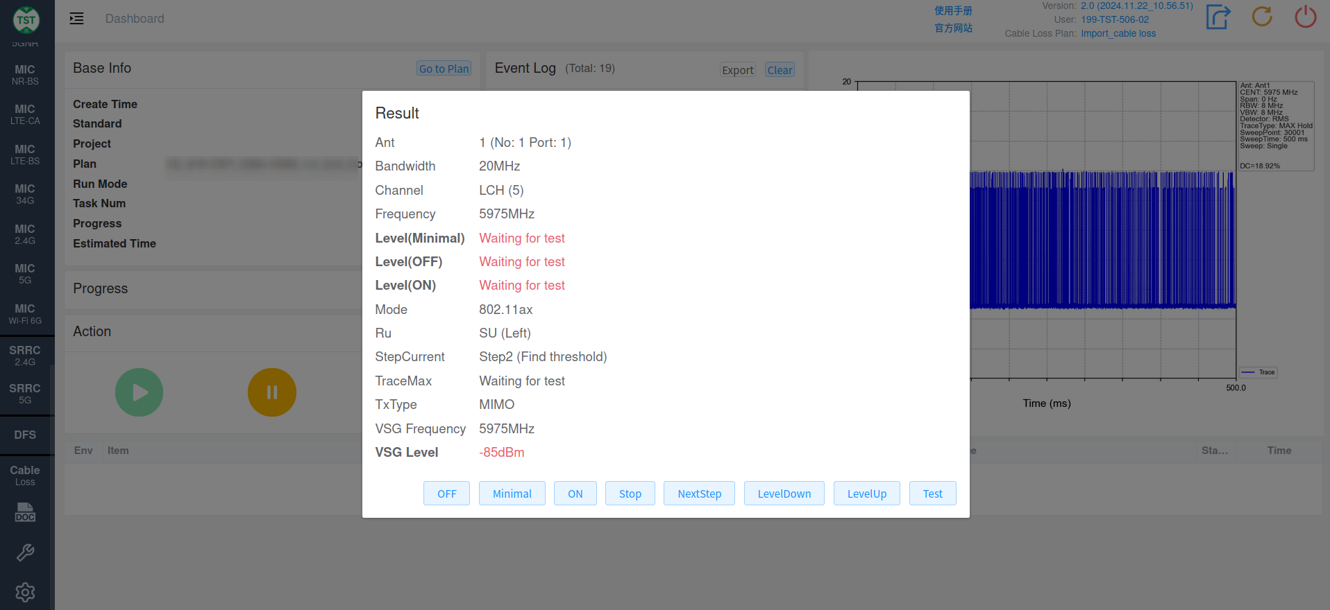
Functions of the buttons in the dialog:
| Button | Function |
|---|---|
| LevelDown | Decrease the VSG level |
| LevelUp | Increase the VSG level |
| Test | Test the actual spectrum at the current VSG level |
| ON | Record the current level as Level (ON) |
| OFF | Record the current level as Level (OFF) |
| Minimal | Record the current level as Level (Minimal) |
| Stop | Stop the test |
| NextStep | Proceed to the next step |
Step 3: Verify the VSG Strength
Following the system prompt, turn off the AWGN signal transmission:
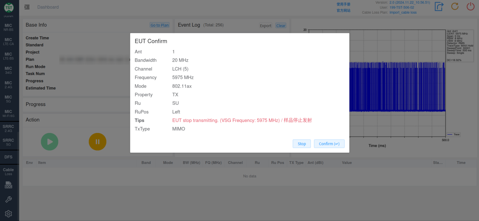
After the verification is complete, resume normal packet transmission as prompted by the system:
Step 4: Detection Probability Test
The system performs at least 10 detection verifications:
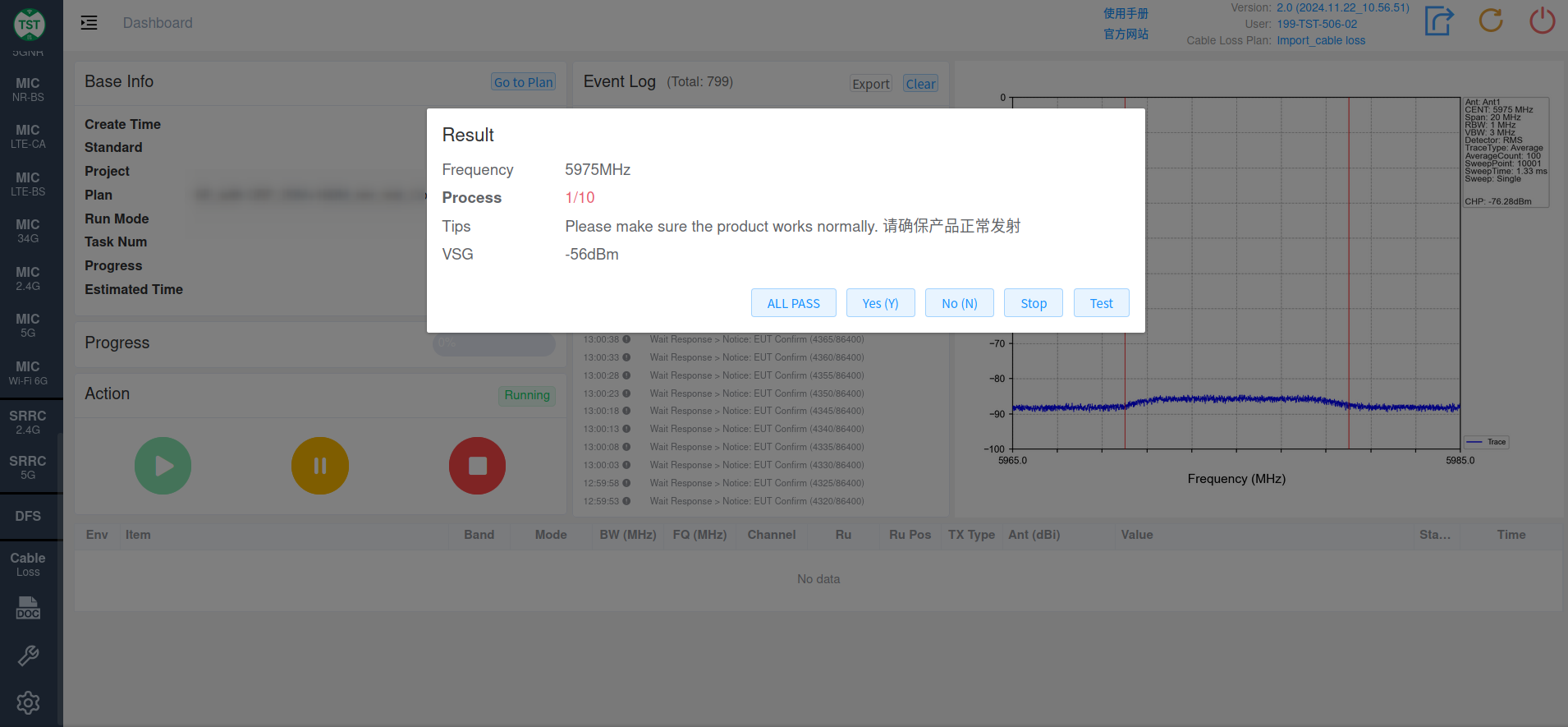
| Button | Function |
|---|---|
| Test | The system automatically judges the current AWGN signal detection |
| Yes | Manually judge the current detection as successful |
| No | Manually judge the current detection as failed |
| All Pass | Manually judge all ten detections as passed |
Note: for each detection, choose either the automatic judgment (Test) or the manual judgment — the two cannot be used at the same time.
Step 5: Interference Stability Test
- The system automatically injects an AWGN signal into the device via the antenna to simulate an incumbent signal and verify the device's response to interference
- Continuous injection is used to observe the device's behavior under prolonged interference
- The system automatically records the device's operating status and performance changes while the interference is present
5.4 Test Completion
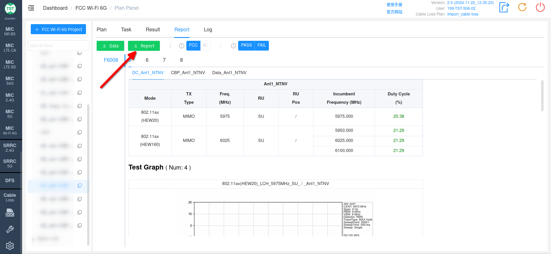
- View the data on the Report page and click the Report button to export the report:
After the Test
Turn off the AWGN signal transmission promptly to prevent interference with subsequent tests.
6. FAQ
Q1: Why is the AWGN signal transmission temporarily switched off in the middle of the CBP test?
According to the regulatory test procedure, switching off the signal transmission in the middle of the test verifies the device's response to interference signals: first confirm that the EUT works normally without external interference, then turn the RF back on and verify that the EUT can immediately (or within the expected time) detect the interference again and stop transmitting. This step evaluates the device's sensitivity and response time to interference and is part of the overall performance evaluation of the device.
Q2: Why are the three levels Level (Minimal) / Level (OFF) / Level (ON) needed?
These three levels represent the device's three response states under different AWGN signal strengths (see Chapter 2 for the definitions): OFF verifies that the device can stop transmitting completely at a specific interference level; Minimal reflects the minimum threshold at which the device begins to sense the interference; ON confirms the upper limit of the level that does not affect transmission. Together, they fully cover the device's behavior at all interference strengths, ensuring reliable operation in real wireless environments.
Q3: Why must the detection probability be tested at least 10 times?
The regulations require verifying that the EUT can detect the AWGN signal with at least 90% certainty (KDB original text):
"Determine and record the AWGN signal power level (at the EUT's antenna port) at which the EUT ceased transmission. Repeat the procedure at least ten times to verify the EUT can detect an AWGN signal with a 90% (or better) level of certainty."
A single test or only a few tests are easily affected by chance; repeating the test many times statistically eliminates random errors and gives the result the level of certainty required by the regulations.