Creating a Test Plan - FCC 2.4G
The FCC 2.4G option is used for North American FCC / IC (ISED) certification testing of unlicensed products in the 2.4 GHz band. When creating a test plan, select the Type (technology) first: WLAN / Bluetooth / BLE / Zigbee / Proprietary. Each type is described separately below.
WLAN
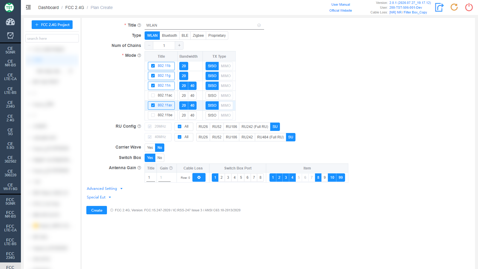
Title: Test plan name, entered by the user, e.g., WLAN / BT / WiFi-Ant1.
Type: Technical category, select WLAN here.
Num of Chains: Number of transmit chains (antennas) the product has.
Mode: Modes supported by the product (required): 802.11b / g / n / ac / ax / be. After checking a mode, select the corresponding Bandwidth (20 / 40 MHz) and TX Type (SISO / MIMO).
RU Config: RU (Resource Unit) configurations supported by 802.11ax / be devices, selected row by row per bandwidth. The Full RU of each bandwidth is required; select the other RU configurations according to the product's actual support. SU (Single User) can be checked separately. Displayed after 802.11ax / be is checked.
Carrier Wave: Whether the product supports carrier wave transmission. If Yes is selected, the frequency error will be measured in carrier wave mode; the test setup differs considerably from the modulated signal test.
Switch Box: Whether to use a Switch Box. If a Switch Box has not been purchased, select No, and the product will be directly connected to the spectrum analyzer for testing.
Antenna Gain:
Title: Antenna number, named sequentially by default as 1, 2, 3, 4..., or manually input other names according to customer requirements.
Gain: Gain of each antenna in the corresponding band (Band).
Cable Loss: Cable loss of the RF cable from the product's antenna port to the Switch Box (RF port of the switch) or the SA (spectrum analyzer). How to Create Common Cable Loss.
Switch Box Port: Port number of the switch connected to the product's antenna, e.g., Ant1 connected to port 1, Ant2 connected to port 2.
Item: Test items for each antenna; the numbers correspond as follows:
(F2401) Duty Cycle
(F2402) Bandwidth
(F2403) Maximum Conducted Output Power
(F2404) Maximum Power Spectral Density
(F2405) Carrier Frequency Separation
(F2406) Number of Hopping Frequencies
(F2407) Time of Occupancy (Dwell Time)
(F2408) Unwanted Emissions In Non-restricted Frequency Bands
(F2409) Unwanted Emissions In Restricted Frequency Bands
(F2410) Frequency Error
(F2499) Form731 — FCC Form 731 report
The software preselects the default test items according to the characteristics of each technology. Note: In some cases, test parameters are mutually referenced between items; if only some items are checked, the test may not be able to proceed. It is recommended to create the test plan with the default items. For multi-antenna products, by default the first antenna performs all applicable items, while for the other antennas the mandatory items have been selected per the standard requirements; non-mandatory items can be checked as needed.
Bluetooth
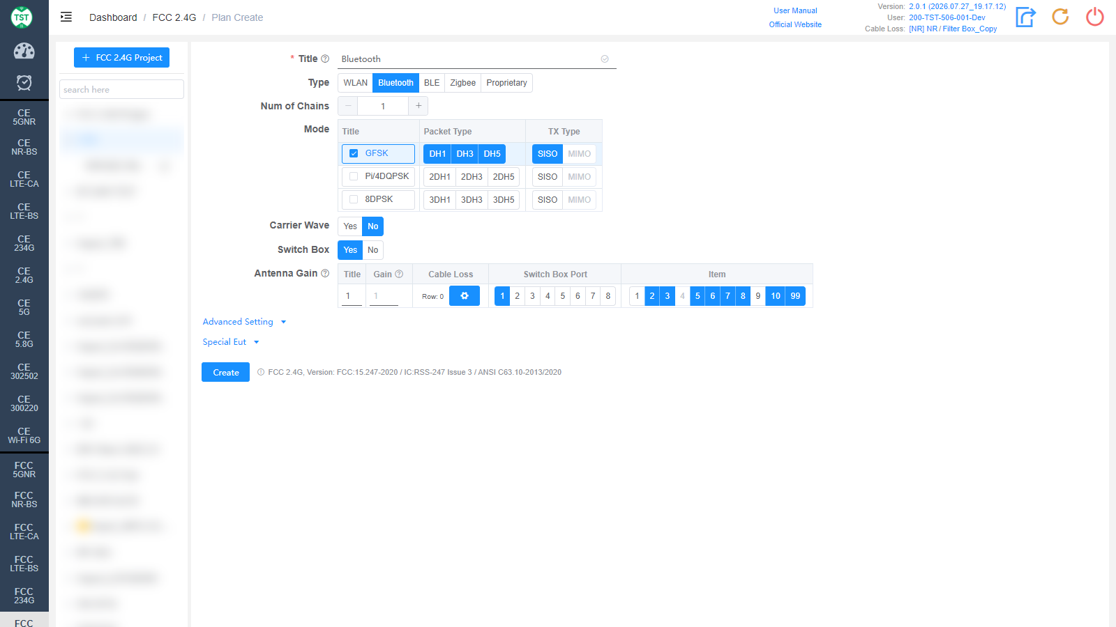
Type: Technical category, select Bluetooth here.
Num of Chains: Number of transmit chains the product has; Bluetooth currently supports only a single antenna.
Mode: Modulations and packet types (Packet Type) supported by the product:
GFSK: BR (Basic Rate), packet types DH1 / DH3 / DH5.
Pi/4DQPSK: EDR 2M, packet types 2DH1 / 2DH3 / 2DH5.
8DPSK: EDR 3M, packet types 3DH1 / 3DH3 / 3DH5.
Carrier Wave / Switch Box / Antenna Gain are the same as WLAN and are not repeated here.
BLE
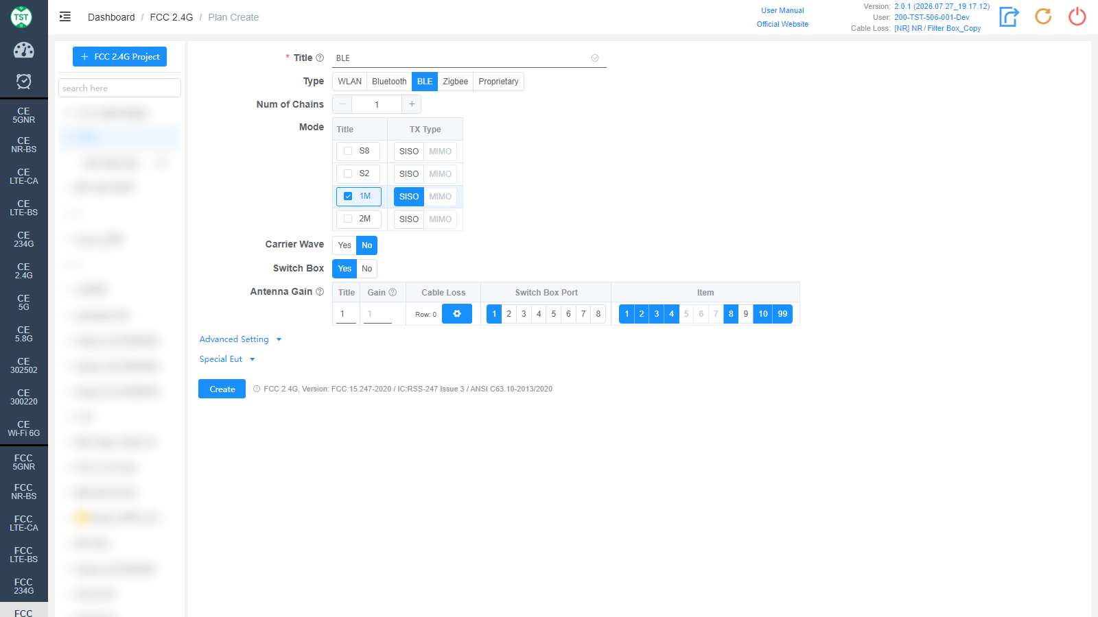
Type: Technical category, select BLE here.
Num of Chains: Number of transmit chains the product has; BLE currently supports only a single antenna.
Mode: Modes supported by the product: S8 / S2 / 1M / 2M. In protocol versions before BT 5.0, BLE only had the 1Mbps rate. Starting from version 5.0, in addition to keeping the 1Mbps rate, two new rates for Long Range scenarios targeting IoT products, S8 and S2 (corresponding to 125kbps and 500kbps respectively), were added, along with the 2Mbps rate for high-bandwidth scenarios. Among them, the 1Mbps rate is mandatory for version 5.0 and above, while the other three rates are optional. In addition, the S8 and S2 rates are implemented by adding FEC (Forward Error Correction) on top of 1Mbps, and their symbol rate is still 1Mbps, so in terms of actual test results, the results of the S8, S2 and 1M modes are basically identical. Therefore, for products that support all three rates, generally only the 1M mode is tested (if S8, S2 and 1M are all selected, the software will test the three modes separately).
Carrier Wave / Switch Box / Antenna Gain are the same as WLAN and are not repeated here.
Zigbee
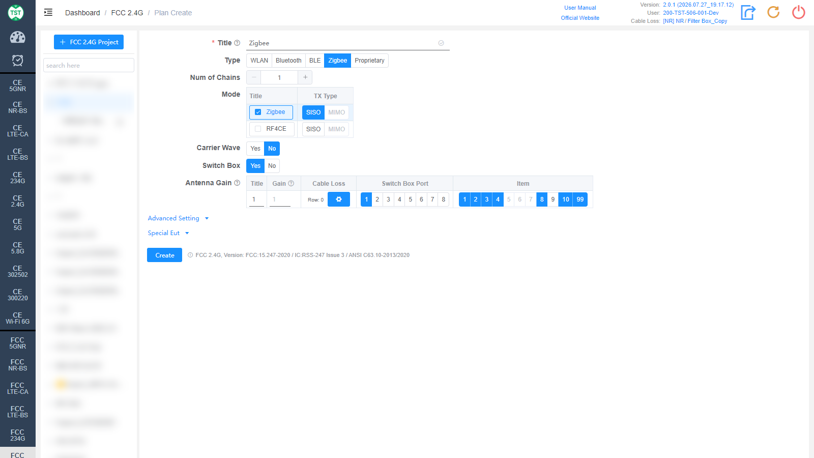
Type: Technical category, select Zigbee here.
Num of Chains: Number of transmit chains (antennas) the product has.
Mode: Modes supported by the product: Zigbee / RF4CE.
Channel: Test channel range: CH11-CH26 or CH11-CH25-CH26. Select according to the channels actually supported by the product.
Carrier Wave / Switch Box / Antenna Gain are the same as WLAN and are not repeated here.
Proprietary

Type: Technical category, Proprietary (custom product).
Num of Chains: Number of transmit chains (antennas) the product has.
Spectrum Spread: Select the spectrum spreading method:
FHSS: Frequency Hopping Spread Spectrum, which transmits the signal by rapidly switching (hopping) among a set of known frequencies, thereby spreading the signal over the spectrum. Its advantages are reduced interference and improved security.
DTS: Digital Transmission System. Systems using digital modulation techniques may operate in the 902-928 MHz, 2400-2483.5 MHz and 5725-5850 MHz bands, and the minimum 6 dB bandwidth shall be at least 500 kHz.
Mode: Custom mode table:
Title: Mode number; other names can be manually input according to customer requirements.
Nominal BW: Sets the nominal bandwidth occupied by the signal on the spectrum.
TX Type: Transmission type, SISO (Single Input Single Output) / MIMO (Multiple Input Multiple Output).
LCH: Low channel setting, used to specify the lowest frequency (MHz) at which communication starts.
MCH: Middle channel setting, used to specify the center frequency of the communication.
HCH: High channel setting, used to specify the highest frequency of the communication.
CSP: Channel Spacing, defining the frequency spacing between channels.
Action: Used to add / delete mode configuration rows.
Carrier Wave / Switch Box / Antenna Gain are the same as WLAN and are not repeated here.
Advanced Setting and Special Eut Settings
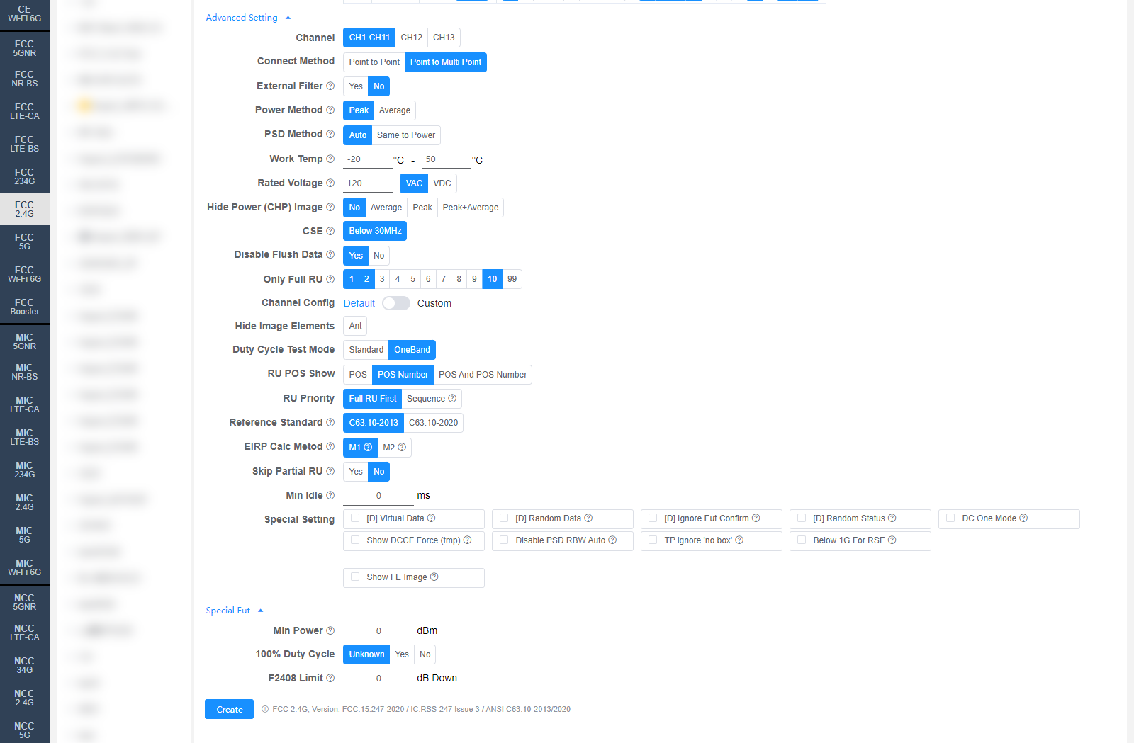
The following settings can generally be kept at their default values. Adjust them only when the test results are abnormal or there are special test requirements. Some fields are only displayed for specific Types, as noted in the descriptions.
Channel (WLAN only): Test channel range, default CH1-CH11 (North American channels). If the product supports CH12 / CH13, they can be checked as well.
Connect Method: Confirm whether the product is a P2P (Point to Point) or P2MP (Point to Multi Point) product, default P2MP. Most common products are P2MP, such as home routers and phones. If the Antenna Gain exceeds 6 dB, this option affects the calculation of the conducted power limit reduction. For details, refer to FCC Part 15.247 (c) eCFR Part 15.247
External Filter: Whether an external filter is used in the RF path during testing.
Manual Confirm (Bluetooth only): Whether a pop-up confirmation is required to confirm that the waveform has stabilized. For items tested in the frequency hopping state, the system's built-in algorithm for automatically determining waveform stability may misjudge because some chips hop very slowly, so this option is enabled by default for Bluetooth, and the test engineer assists in determining whether the waveform has stabilized.
Power Method: Confirm whether the Conducted Power is measured using the Peak or Average method.
PSD Method: Measurement method for the Power Spectral Density: Auto (automatically selected per the regulations) or Same to Power (same as the total output power measurement).
Work Temp: Operating temperature range (°C) of the product. Affects the frequency stability test.
Rated Voltage: Rated operating voltage (VAC / VDC) of the product. Affects the frequency stability test.
Hide Power (CHP) Image: Option to hide the CHP power images in the report: No / Average / Peak / Peak+Average, applicable to the F2403 report.
CSE: Conducted Spurious Emissions setting. When Below 30MHz is enabled, the three segments 9 kHz ~ 150 kHz / 150 kHz ~ 10 MHz / 10 MHz ~ 30 MHz are additionally tested. The default value can be changed on the Setting page.
Disable Flush Data: Whether to disable data flushing. When disabled, CSE is subject to the same restriction; the default value can be changed on the Setting page.
Channel Config: Channel configuration, Default or Custom (manually customized channels).
Hide Image Elements: Select the elements to hide in report images (e.g., the Ant antenna marker).
Duty Cycle Test Mode: Duty cycle test mode: Standard / OneBand (single channel).
RU POS Show: How the RU position is displayed in the report: POS / POS Number / POS And POS Number.
RU Priority: RU test priority: Full RU First or Sequence (in the order RU26 → RU52 → RU106...).
Reference Standard: Select the reference standard for testing: C63.10-2013 (for F2402 6dB BW, Rbw=100kHz Vbw=300kHz) or C63.10-2020 (for F2402 6dB BW, Rbw=360kHz Vbw=1.1MHz).
EIRP Calc Metod: EIRP calculation method for MIMO:
M1: EIRP (MIMO) = EIRP_ANT1 + EIRP_ANT2 (converted to mW for summation, then converted back to dBm).
M2: EIRP (MIMO) = Conducted Power_MIMO + Directional Gain.
Min Idle: Minimum idle time (ms) for the duty cycle test.
Special Setting: Special settings. Options prefixed with [D] are debug options and do not need to be checked for normal testing:
[D] Virtual Data / [D] Random Data / [D] Ignore Eut Confirm / [D] Random Status: Debug options.
DC One Mode: Only one duty cycle is tested per mode, e.g., 802.11b only measures the duty cycle of the LCH.
Show DCCF Force (tmp): Temporary option to force the DCCF to be displayed in the F2403 / F2404 images.
Disable PSD RBW Auto: Disables automatic RBW adjustment for the PSD measurement.
TP ignore 'no box': Test Priority ignores the "no switch box" scenario. By default, in the no-switch-box scenario, fixed-frequency antennas have the lowest priority.
Below 1G For RSE: When checked, the RSE test will include frequencies below 1 GHz.
Show FE Image: When checked, the frequency error images are displayed (all displayed by default).
Min Power: Sets the minimum power (dBm); 0 means automatic.
100% Duty Cycle: Whether the sample's duty cycle is 100% (Unknown / Yes / No); only needs to be selected when the system misjudges the duty cycle.
F2408 Limit: Sets the value (dB Down) to be subtracted from the Level of Reference in F2408; the result is the Limit. Setting 0 means automatic, calculated per the standard regulations.
Referenced regulations (displayed next to the Create button): FCC 2.4G, Version: FCC:15.247-2020 / IC:RSS-247 Issue 3 / ANSI C63.10-2013/2020