System Cable Loss Calibration (Using Switch Box as an Example)
Calibration Preparation:
Hardware Preparation:
- Spectrum Analyzer
- Analog Signal Generator (ASG)
- Switch Box
- Five RF cables, namely:
TST-REF: Used for REF test, as a reference line
TST-BS: Used for BS line test
TST-SA: Used for SA line test
TST-ASG: Used for ASG line test
TST-VSG: Used for VSG line test
- Three 50Ω terminations (loads), used to terminate the ports not being calibrated
Software Preparation:
- TST PASS RF Automated Test System
Cable Loss Plan Settings:
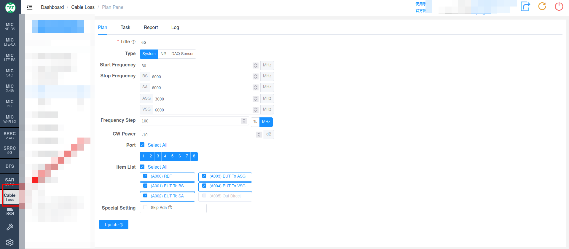
- In Cable Loss, create a Cable Loss Project and then create a Plan
- Select the test type (System, NR, or DAQ Sensor)
- Set the Stop Frequency for the corresponding device
- Set the corresponding Frequency Step
- Select the corresponding Port based on the number of ports on the Switch Box
- Select the Item to be tested
- Click Update to save the settings and prepare for cable loss calibration
Calibration Notes:
About the "EUT to XX" Calibration Items
"EUT to BS / SA / ASG / VSG" are the names of the calibration items in the system. During cable loss calibration, the EUT position is actually connected to an ASG (Analog Signal Generator), not the device under test.
Important: Terminate the Remaining Ports with 50Ω Loads
There are four ports on the back of the Switch Box: BS, SA, ASG, and VSG. When calibrating the line of any one of these ports, the remaining 3 ports must be terminated with 50Ω loads to ensure impedance matching and avoid affecting calibration accuracy. In the block diagrams below, the ports that need to be terminated are marked with "50Ω Termination".
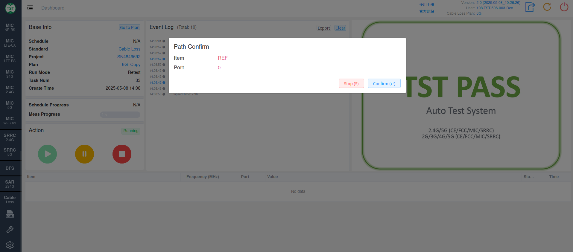
REF:
Software Prompt (as shown):
Hardware Connection:
Operation:
- At this time, the Switch Box does not require any connection
- Use TST-REF to connect the ASG to the SA
- After connecting, click confirm, and the system will automatically test REF
EUT to BS:
Software Prompt (as shown):

Hardware Connection:
Operation:
- Use TST-REF to connect the ASG to the corresponding port indicated by the system (ASG to the front port of the Switch Box)
- Use TST-BS to connect the SA to the corresponding port indicated by the system (SA to Port BS on the rear of the Switch Box)
- Terminate the remaining 3 rear ports (Port SA, Port ASG, Port VSG) with 50Ω loads
- After the devices are connected, click confirm, and the system will automatically test EUT to BS
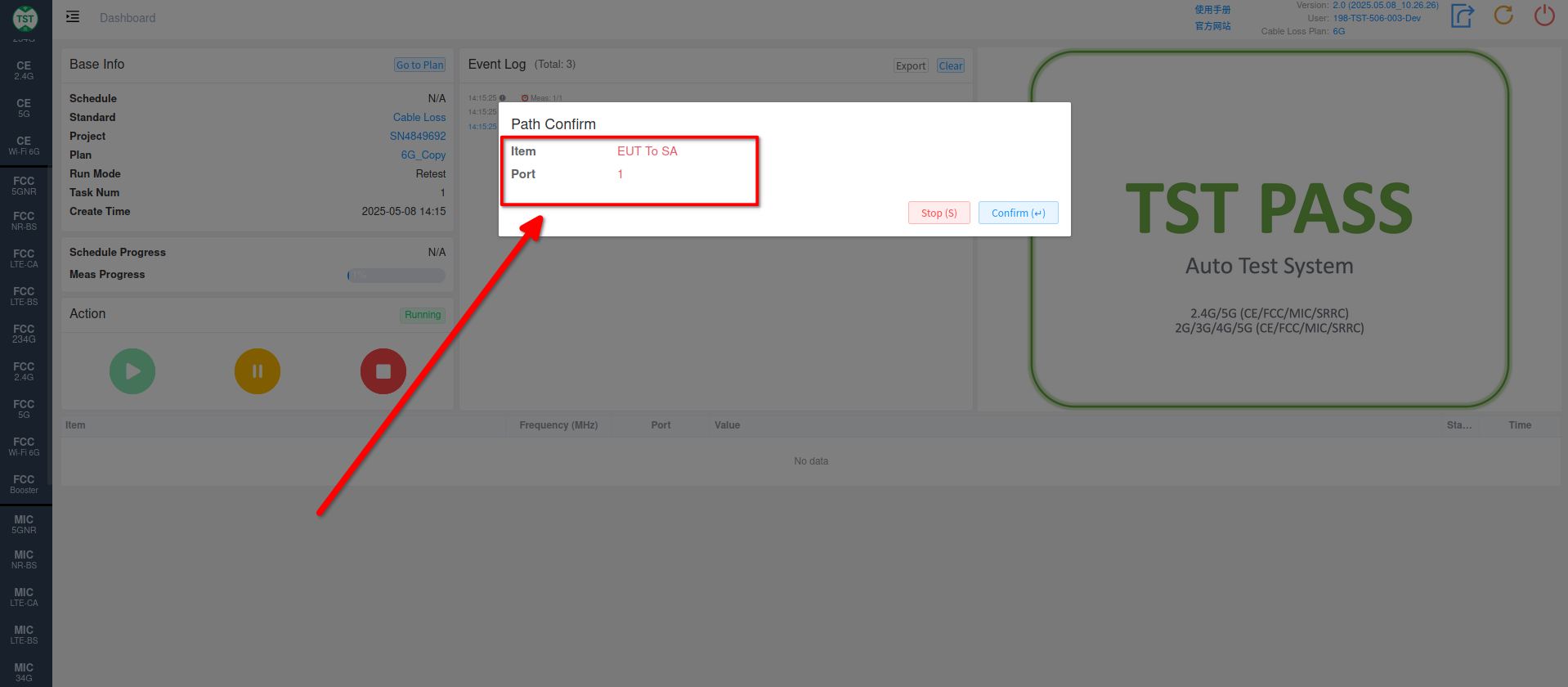
EUT to SA:
Software Prompt (as shown):
Hardware Connection:
Operation:
- Use TST-REF to connect the ASG to the corresponding port indicated by the system (ASG to the front port of the Switch Box)
- Use TST-SA to connect the SA to the corresponding port indicated by the system (SA to Port SA on the rear of the Switch Box)
- Terminate the remaining 3 rear ports (Port BS, Port ASG, Port VSG) with 50Ω loads
- After the devices are connected, click confirm, and the system will automatically test EUT to SA
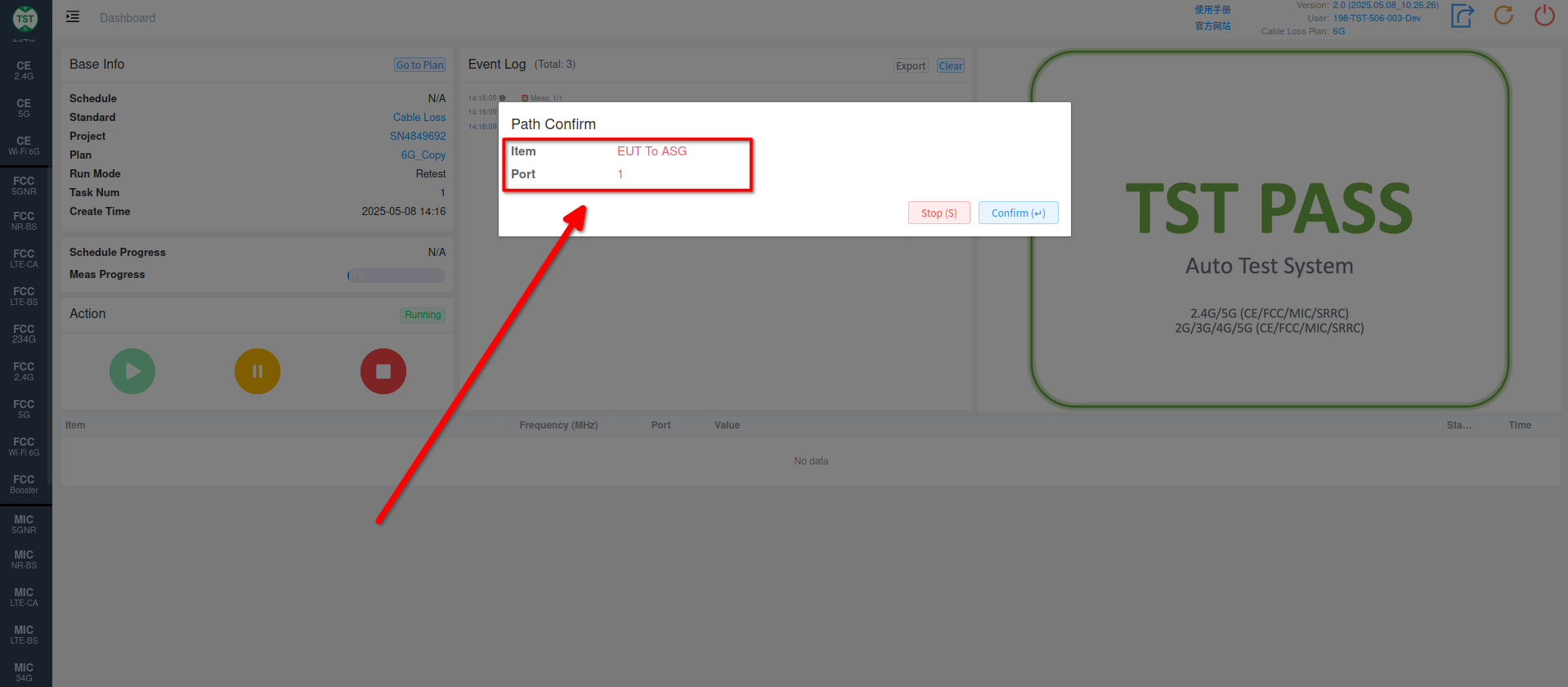
EUT to ASG:
Software Prompt (as shown):
Hardware Connection:
Operation:
- Use TST-REF to connect the ASG to the corresponding port indicated by the system (ASG to the front port of the Switch Box)
- Use TST-ASG to connect the SA to the corresponding port indicated by the system (SA to Port ASG on the rear of the Switch Box)
- Terminate the remaining 3 rear ports (Port BS, Port SA, Port VSG) with 50Ω loads
- After the devices are connected, click confirm, and the system will automatically test EUT to ASG
EUT to VSG:
Software Prompt (as shown):
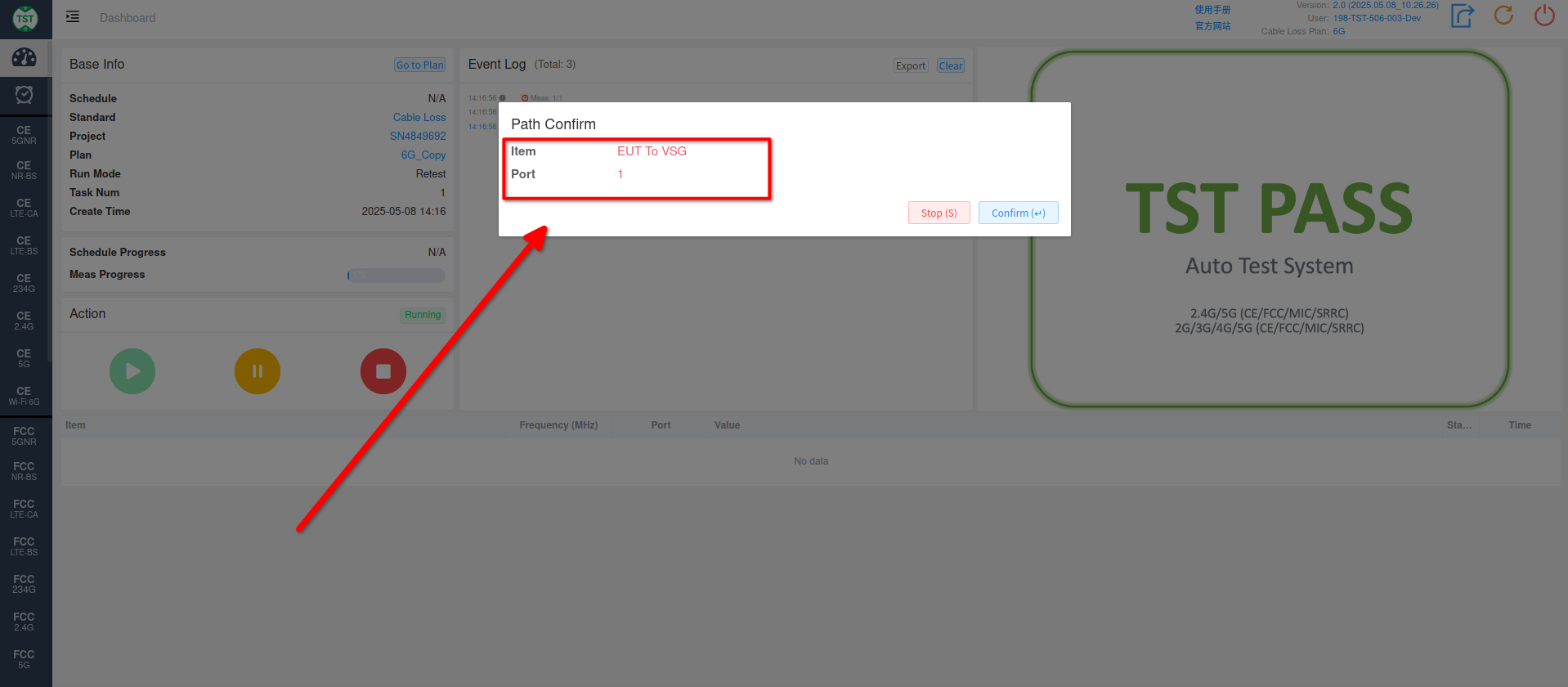
Hardware Connection:
Operation:
- Use TST-REF to connect the ASG to the corresponding port indicated by the system (ASG to the front port of the Switch Box)
- Use TST-VSG to connect the SA to the corresponding port indicated by the system (SA to Port VSG on the rear of the Switch Box)
- Terminate the remaining 3 rear ports (Port BS, Port SA, Port ASG) with 50Ω loads
- After the devices are connected, click confirm, and the system will automatically test EUT to VSG
Set Test Results as System Cable Loss:
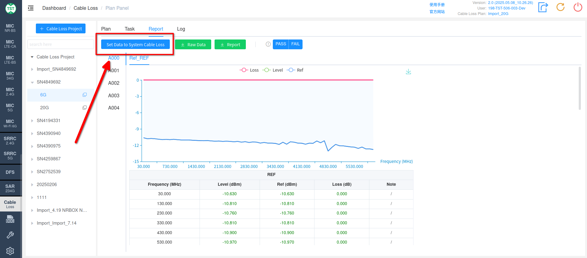
In the Task or Report section, click Set data to system cable loss to use the calibration results as the system's Cable Loss