DFS Test Standard Operating Procedure
Scope: RLAN devices operating in the 5 GHz DFS bands — FCC U-NII-2A (5250 ~ 5350 MHz) and U-NII-2C (5470 ~ 5725 MHz); CE Band 2 (5250 ~ 5350 MHz) and Band 3 (5470 ~ 5725 MHz)
Reference standards: FCC §15.407(h)(2), FCC KDB 905462 D02; EN 301 893 (§4.2.6); ITU-R M.1652
Corresponding TSTPASS module: DFS (in the standards column on the left side of the system)
1. Overview
DFS (Dynamic Frequency Selection) is a mandatory radio interference mitigation mechanism for 5 GHz RLAN devices. The primary users of the 5250 ~ 5350 MHz and 5470 ~ 5725 MHz bands are radiolocation services such as weather radars and airborne radars. When RLAN devices access these bands as secondary users, they must be capable of detecting radar signals and actively vacating the channel.
The purpose of DFS testing is to verify, using the radar test waveforms defined by the regulations, whether the device meets the requirements for radar detection, transmission shutdown, channel move, and channel non-occupancy in both the startup phase and the in-service phase.
2. Terminology and Test Items
2.1 Device Operation Flow
2.2 Test Item Definitions
| Test Item | Definition | FCC Requirement | EN 301 893 Requirement |
|---|---|---|---|
| CAC (Channel Availability Check) | Silent monitoring before the first use of a DFS channel | ≥ 60 s | ≥ 60 s; 10 min for the weather channels (5600 ~ 5650 MHz) |
| Channel Move Time | Total time to complete the channel move after radar detection | ≤ 10 s | ≤ 10 s |
| Channel Closing Transmission Time | Transmission time allowed during the channel move | 200 ms + an aggregate of ≤ 60 ms over the remaining time | Aggregate ≤ 1 s |
| Non-Occupancy Period | Period during which a channel where radar was detected must not be used | ≥ 30 min | ≥ 30 min |
| In-Service Monitoring | Continuous monitoring of the channel during operation | Throughout operation | Throughout operation |
2.3 Radar Detection Threshold and Test Waveforms
| Maximum EIRP of the Device | Detection Threshold (normalized to a 0 dBi receive antenna) |
|---|---|
| ≥ 200 mW (23 dBm) | -64 dBm |
| < 200 mW (23 dBm) | -62 dBm |
In actual testing, the radar signal level applied to the EUT antenna port is usually set to the threshold value +1 dB (e.g., -62 + 1 = -61 dBm) to ensure the signal is at a detectable level.
FCC radar test waveforms (defined in KDB 905462 D02):
| Waveform | Type | Detection Probability Requirement |
|---|---|---|
| Radar Type 0 ~ 4 | Short pulse radar | ≥ 60% for each type; ≥ 80% aggregate for Types 1 ~ 4 |
| Radar Type 5 | Long pulse radar (LFM chirp) | ≥ 80% |
| Radar Type 6 | Frequency hopping radar | ≥ 70% |
For the specific parameters of each waveform (pulse width, PRI, number of pulses, etc.), refer to the tables in KDB 905462 D02; for the EN 301 893 radar test signals (Pattern 1 ~ 6), refer to its Annex D. The TSTPASS system has built-in radar waveform libraries for each regulation, which are invoked automatically during testing.
3. Device Roles and Test Object
3.1 Determining the Test Object for Master / Slave
| Product Type | Radar Detection Capability | Device Connected to the DUT Port | Device Connected to the AE Port |
|---|---|---|---|
| Master | Yes | Sample itself | Slave (e.g., a mobile phone) |
| Slave with radar detection | Yes | Sample itself | Auxiliary Master |
| Slave without radar detection | No | Auxiliary Master (AP) | Sample itself |
Note
Per FCC KDB 905462 and EN 301 893: for a Master or a Slave without radar detection, the radar signal is always applied directly to the Master. Therefore, when the sample is a Slave without radar detection, the DUT referred to here is the auxiliary AP (Master) used for the test, not the sample itself — the sample must be connected to the AE port.
3.2 Auxiliary Equipment and Software
- Auxiliary Equipment (AE): the paired device that establishes the communication link with the DUT (a Slave such as a mobile phone when the sample is a Master; an auxiliary Master such as an AP when the sample is a Slave)
- Traffic generation software: e.g., iperf3, used to establish a data stream between the DUT and the AE that meets the duty cycle requirement
4. Test System Composition and Connection
4.1 Test Instruments
| Equipment | Function |
|---|---|
| Vector Signal Generator (VSG) | Generates the radar test waveforms defined by the regulations |
| Spectrum Analyzer (SA) | Observes the radar signal and the EUT signal |
| Control box (or power splitter) | RF path switching (use a power splitter for a manually built setup) |
| Adjustable attenuator (ATT) | Adjusts the displayed strength of the EUT signal on the SA |
4.2 Setup Block Diagram
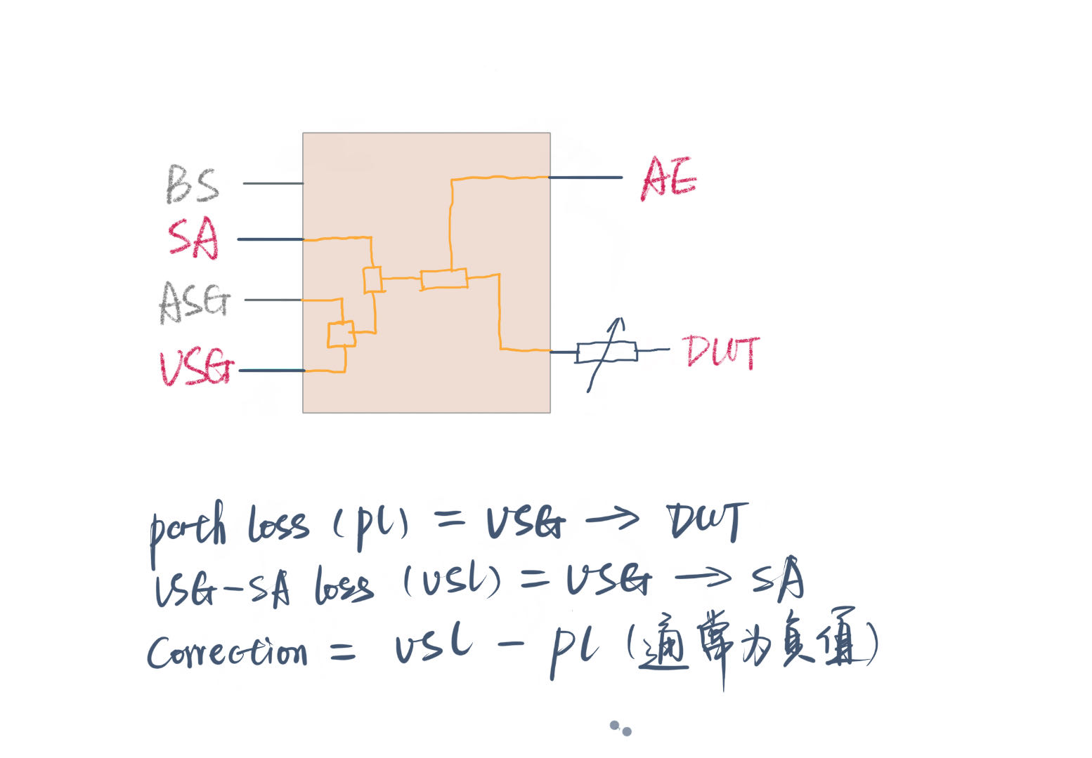
The Path Loss and Correction in the diagram correspond to the parameters of the same names on the Plan page of the TSTPASS system:
Signal paths:
| Path | Function |
|---|---|
| VSG → splitter → SA | Radar signal observation |
| VSG → splitter → ATT → DUT | Radar signal injection |
| DUT ↔ AE | Communication link (traffic) |
5. TSTPASS Pure Visual Approach
5.1 Approach Comparison
TSTPASS performs DFS testing with a pure visual approach: the spectrum analyzer observes the radar signal and the EUT signal simultaneously, so the entire process of detection, transmission shutdown, and channel move is presented directly in the test data.
| Aspect | Trigger Approach | Pure Visual Approach |
|---|---|---|
| Setup complexity | Simple | Relatively complex |
| Learning curve | Low | Higher |
| Radar signal visibility | Not directly observable in the test data | Presented on the same screen as the EUT signal |
| Data credibility | May be questioned by reviewers | Intuitive and indisputable |
Each approach has its pros and cons. The Trigger approach is simple to set up and easy to understand, but the radar signal cannot be seen in the test data, so the data may be questioned. The pure visual approach has a more complex setup and a higher learning curve, but once mastered, it provides a much more thorough understanding of the entire DFS test, and the test data is intuitive and leaves no room for dispute.
Important
The pure visual approach is fundamentally different from the Trigger approach — do not apply Trigger-approach thinking to the pure visual approach. In the pure visual approach, the spectrum analyzer serves only as an observation tool, and the signal strength displayed on the spectrum analyzer is not the true signal strength — the true strength is derived through the Path Loss and Correction values.
5.2 Core Requirement: The 6 dB Visual Criterion
The pure visual approach has only one requirement: the radar signal observed on the SA must be more than 6 dB above the EUT signal, so that the radar signal can be clearly distinguished in the test plots.
5.3 Adjustment Principle of the Adjustable Attenuator (ATT)
With a direct connection, the 6 dB criterion cannot be met. Take FCC as an example: if the EIRP of the EUT is 22 dBm (< 23 dBm, so the detection threshold is -62 dBm), the applied radar signal level should be -62 + 1 = -61 dBm. If both signals were connected directly to the SA, the radar signal would be about 22 - (-61) = 83 dB below the EUT signal — impossible to distinguish.
The solution is to adjust the adjustable attenuator at the EUT front end. Assume the ATT is increased by 20 dB; this produces three effects at the same time:
- The EUT signal observed on the SA decreases by 20 dB;
- The path loss from the VSG to the EUT increases by 20 dB. To keep the radar signal arriving at the EUT antenna port at -61 dBm, the VSG output level must be raised by 20 dB accordingly;
- The path loss between the VSG and the SA is unchanged, so the radar signal observed on the SA actually increases by 20 dB.
The gap between the two signals on the SA then narrows to (22 - 20) - (-61 + 20) = 43 dB. Continue increasing the ATT in the same way until "radar signal - EUT signal ≥ 6 dB" is satisfied.
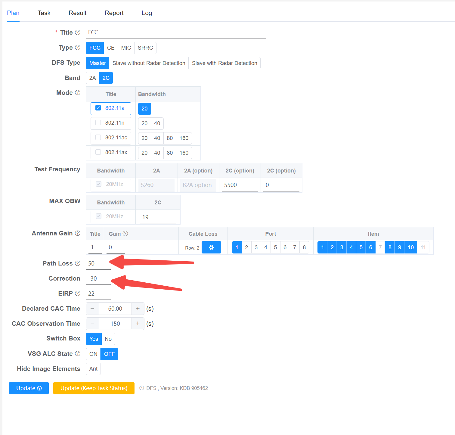
5.4 Path Loss and Correction
| Parameter | Definition | Purpose |
|---|---|---|
| Path Loss | The measured path loss from the VSG to the EUT input after the ATT adjustment is completed | The system uses it to set the VSG output level so that the radar signal arriving at the EUT is at the target level |
| Correction | The difference between the target radar level and the level observed on the SA | The system applies it to the data acquired from the SA so that the radar signal strength presented in the report is the true level |
Example: the required radar signal level is -61 dBm and the radar signal observed on the SA is -20 dBm, so Correction = -61 - (-20) = -41 dB. The system applies this correction to the test data, and the radar signal is displayed as -61 dBm in the final report.
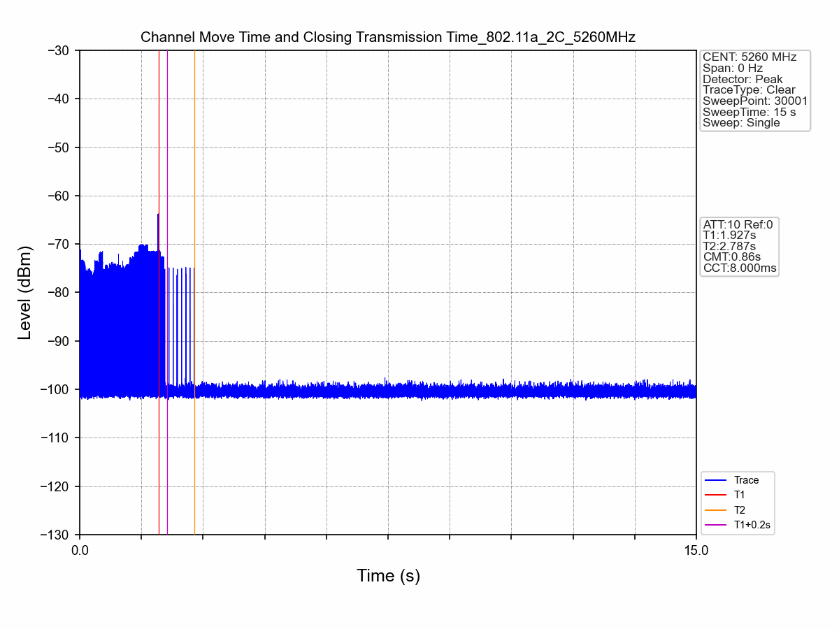
5.5 Test Data Example
The figure below shows DFS test data produced by TSTPASS: the radar pulse burst and the EUT signal are presented on the same screen, and the channel vacating behavior is evident at a glance.
6. Key Points for Test Execution
- For the CAC test, powering on the sample must be synchronized with starting the test in the system — CAC timing starts from power-on; if they are not synchronized, the timing window is misaligned and the test is invalid
- Before testing, confirm that the Path Loss and Correction on the Plan page have been measured and filled in according to the method in Chapter 5
- Before the in-service phase tests (Channel Move / Closing Time), confirm that traffic between the DUT and the AE is running normally and that the duty cycle meets the regulatory requirement
- Turn off the VSG output promptly after the test to avoid interference with subsequent tests
Troubleshooting
| Symptom | Possible Cause | Solution |
|---|---|---|
| Radar signal not clearly visible on the SA | Improper ATT setting; the 6 dB criterion is not met | Re-adjust the ATT per Section 5.3 and re-measure the Path Loss |
| CAC test fails | Sample power-on not synchronized with test start | Repeat the test, ensuring power-on and test start are synchronized |
| Test data questioned by reviewers | Trigger approach used; no radar signal in the data | Switch to the pure visual approach |
7. Regulatory References
| Regulation | Region | Content |
|---|---|---|
| FCC §15.407(h)(2) / KDB 905462 D02 | North America | DFS requirements, compliance test procedures, and radar test waveforms |
| EN 301 893 | European Union | Harmonised standard for 5 GHz RLAN; DFS requirements in §4.2.6, radar test signals in Annex D |
| ITU-R M.1652 | International | DFS requirements for the coexistence of RLAN with radiolocation services |