External Calibration
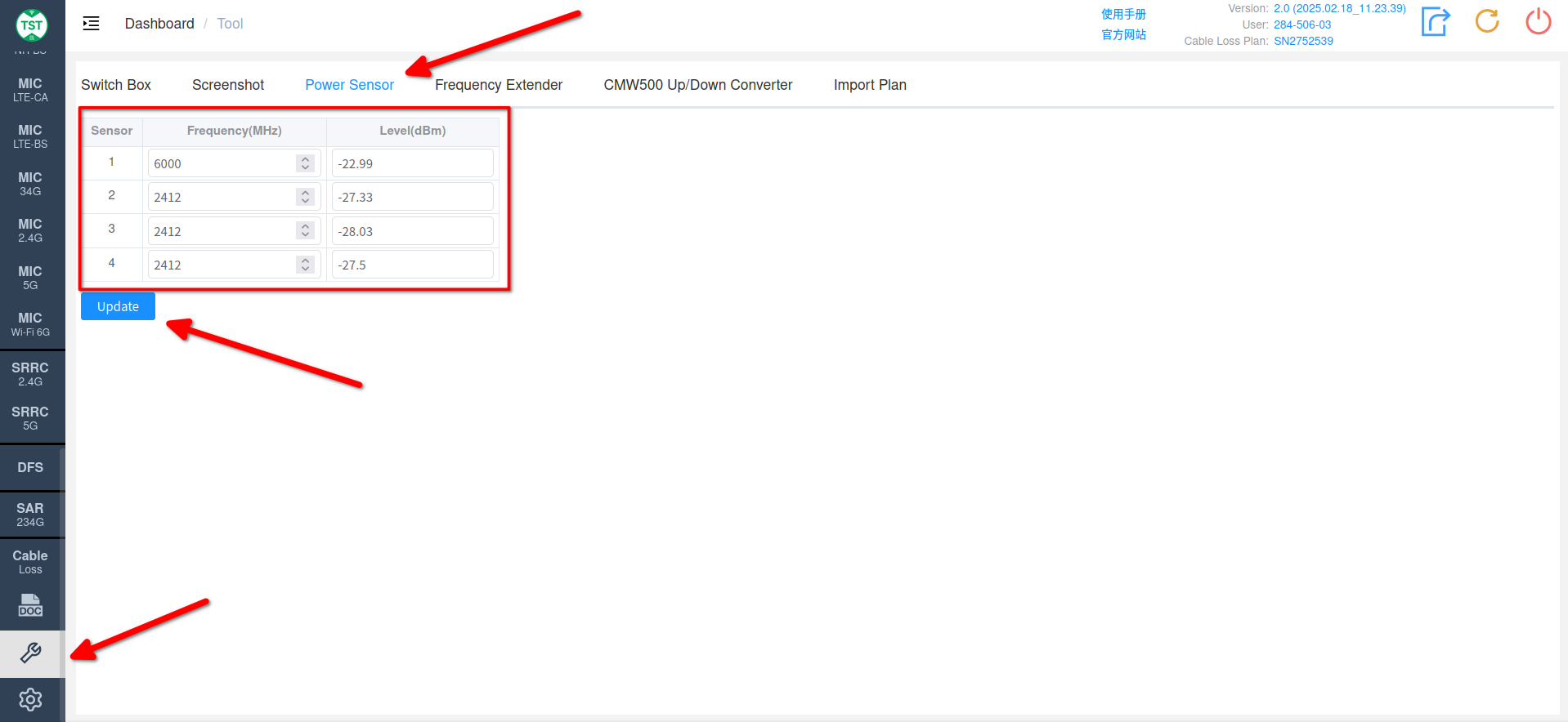
Power Sensor Calibration
- As shown in the figure below, switch to Tools -> Power Sensor page.
- Take calibrating Port 1 as an example:
- Connect the output end of the signal generator to Port 1 of the switch box.
- Set the output frequency (e.g., 2400) and power P0 of the signal generator.
- Enter the measurement frequency of Sensor 1 2400 in the system.
- Click Update to read the Level value P1 corresponding to Sensor 1.
- Compare the results of P1 and P0 to calculate the deviation.
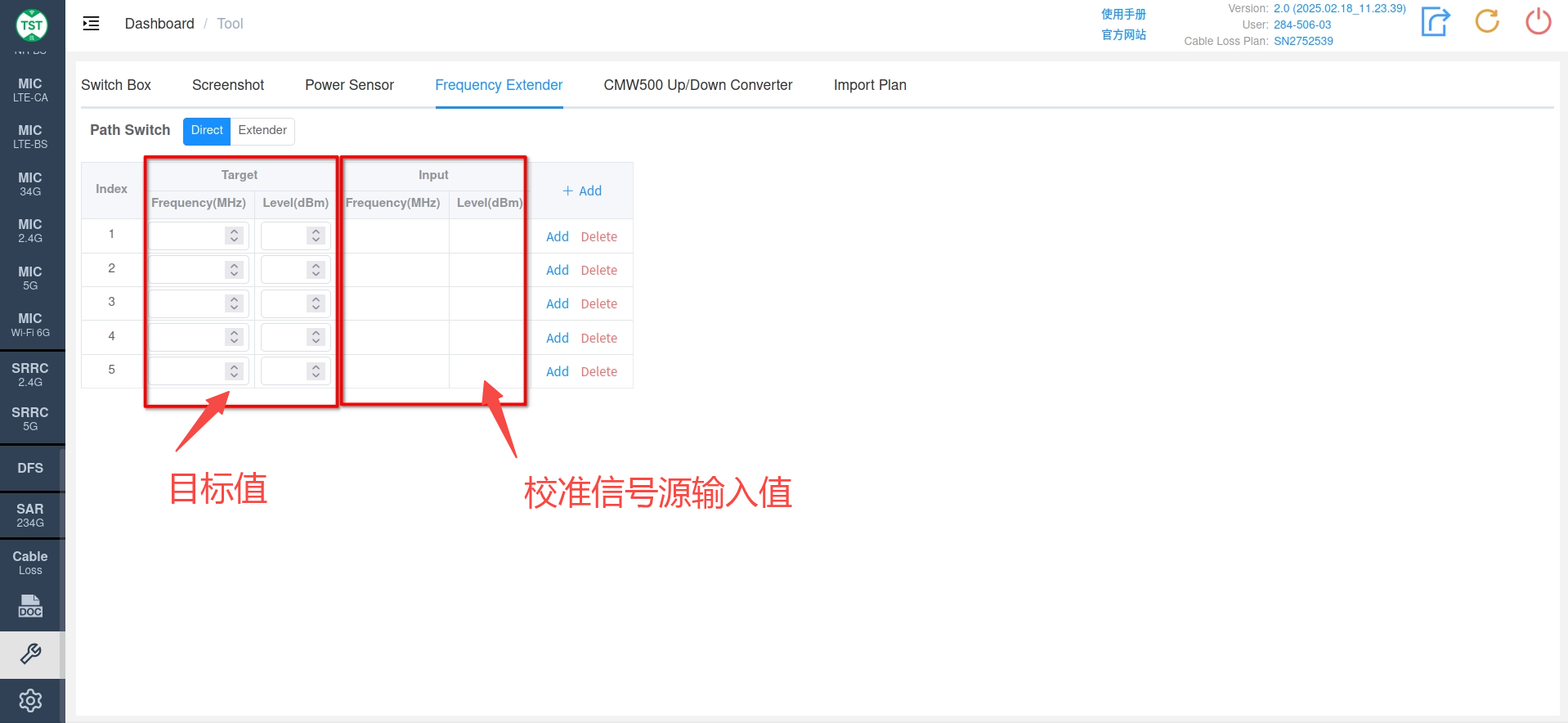
Vector Signal Generator Frequency Extender Calibration
As shown in the figure below, switch to Tools -> Frequency Extender page.
Hardware Connection:
- Connect the output end of the calibration signal generator to the input end of the frequency extender.
- Connect the input end of the calibration power meter (or spectrum analyzer) to the output end of the frequency extender.
Path Switch switches the path to be calibrated.
Direct: The direct path of the signal generator, i.e., the output signal frequency of the frequency extender = the input frequency of the signal generator.
Extender: The extender path, the input frequency of the signal generator is output after being extended by the frequency extender.
In the Target input box, enter the frequency and power level to be calibrated. The system will automatically calculate the frequency and power level that the calibration signal generator should input (Frequency and Level displayed in the Input window) based on the factory calibration data of the frequency extender.
Set the calibration signal generator according to the Frequency and Level displayed in the Input window. The calibration power meter (or spectrum analyzer) reads the power level of the frequency displayed in the Target window.
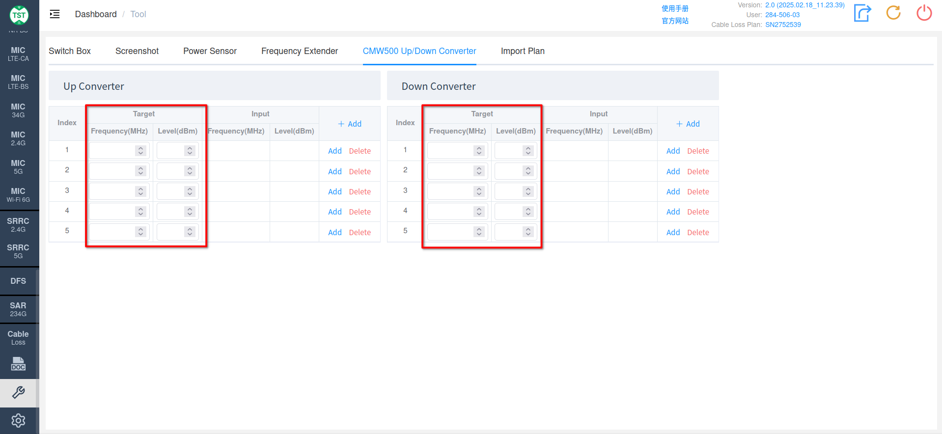
Comprehensive Tester Up/Down Converter Calibration
As shown in the figure below, switch to Tools -> CMW500 Up/Down Converter page.
Hardware Connection:
Up Converter Calibration:
- Connect the output end of the calibration signal generator to the input end of the converter (RF COM2).
- Connect the input end of the calibration power meter (or spectrum analyzer) to the output end of the converter (To DUT).
Down Converter Calibration:
- Connect the output end of the calibration signal generator to the input end of the converter (From DUT).
- Connect the input end of the calibration power meter (or spectrum analyzer) to the output end of the converter (RF COM1).
In the Target input box, enter the frequency and power level to be calibrated. The system will automatically calculate the frequency and power level that the calibration signal generator should input (Frequency and Level displayed in the Input window) based on the factory calibration data of the frequency extender.
Set the calibration signal generator according to the Frequency and Level displayed in the Input window. The calibration power meter (or spectrum analyzer) reads the power level of the frequency displayed in the Target window.