
Creating a Test Plan - CE 5.8G
The CE 5.8G option is used for EU CE (RED) certification testing of Short Range Devices (SRD) in the 1 GHz ~ 40 GHz range per EN 300 440. It is commonly used for SRD products in the 2.4 GHz / 5.8 GHz bands and covers both transmitter and receiver parameters. When creating a test plan, select the Type (technology) first: RLAN / Proprietary. Each type is described separately below.
RLAN
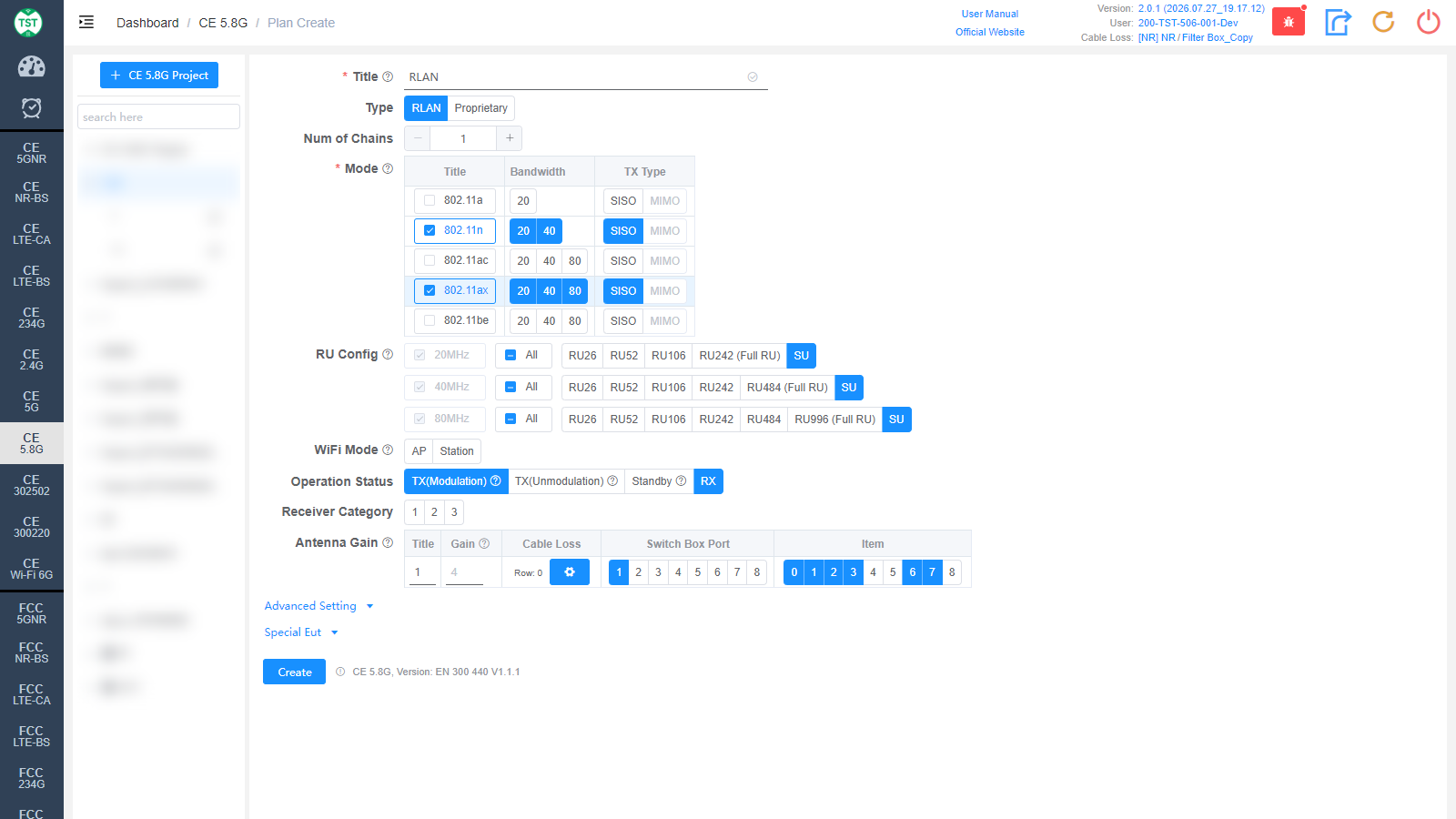
Title: Test plan name, entered by the user.
Type: Technical category, select RLAN here.
Num of Chains: Number of transmit chains (antennas) the product has.
Mode: Modes supported by the product (required): 802.11a / n / ac / ax / be. After checking a mode, select the corresponding Bandwidth (20 / 40 / 80 MHz) and TX Type (SISO / MIMO).
RU Config: RU (Resource Unit) configurations supported by 802.11ax / be devices. The Full RU of each bandwidth is required; select the other RU configurations according to the product's actual support. Displayed after 802.11ax / be is checked.
WiFi Mode: WiFi role of the EUT: AP (wireless access point) / Station (client).
Operation Status: Operating states of the product to be tested, multi-select:
TX(Modulation): Modulated signal transmission state.
TX(Unmodulation): Carrier wave (unmodulated) transmission state.
Standby: Standby state.
RX: Receive state.
Receiver Category: Receiver category: 1 / 2 / 3. EN 300 440 classifies receivers into three categories according to the product's use; the category affects the applicability and limits of the receiver parameters. Select according to the category declared for the product.
Antenna Gain:
Title: Antenna number, named sequentially by default as 1, 2, 3, 4....
Gain: Gain of each antenna.
Cable Loss: Cable loss of the RF cable from the product's antenna port to the Switch Box or the SA (spectrum analyzer). How to Create Common Cable Loss.
Switch Box Port: Port number of the switch connected to the product's antenna.
Item: Test items for each antenna; the numbers correspond as follows:
(C44000) Duty Cycle
(C44001) -6dB Bandwidth
(C44002) Equivalent isotropically radiated power (e.i.r.p.)
(C44003) Permitted range of operating frequencies
(C44004) Unwanted emissions in the spurious domain (TxSe)
(C44005) Unwanted emissions in the spurious domain (Standby)
(C44006) Adjacent channel selectivity
(C44007) Blocking or desensitization
(C44008) Spurious radiations
The software preselects the default test items according to the technical characteristics. Note: In some cases, test parameters are mutually referenced between items; it is recommended to create the test plan with the default items.
Proprietary
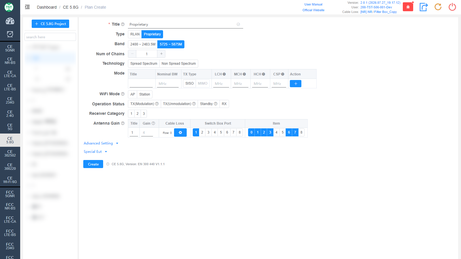
Type: Technical category, Proprietary (custom product).
Band: Operating band of the product: 2400 ~ 2483.5M or 5725 ~ 5875M.
Technology: Modulation technology of the product: Spread Spectrum / Non Spread Spectrum.
Mode: Custom mode table:
Title: Mode number; other names can be manually input according to customer requirements.
Nominal BW: Sets the nominal bandwidth occupied by the signal on the spectrum.
TX Type: Transmission type, SISO / MIMO.
LCH / MCH / HCH: Low / middle / high channel frequency settings (MHz).
CSP: Channel Spacing.
Action: Used to add / delete mode configuration rows.
WiFi Mode / Operation Status / Receiver Category / Antenna Gain are the same as RLAN and are not repeated here.
Advanced Setting and Special Eut Settings
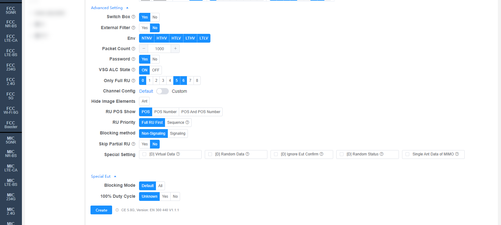
The following settings can generally be kept at their default values. Adjust them only when the test results are abnormal or there are special test requirements.
Switch Box: Whether to use a Switch Box. If a Switch Box has not been purchased, select No, and the product will be directly connected to the spectrum analyzer for testing.
External Filter: Whether an external filter is used in the RF path during testing.
Env: Environmental conditions to test, multi-select: NTNV / HTHV / HTLV / LTHV / LTLV (normal temp normal volt / high temp high volt / high temp low volt / low temp high volt / low temp low volt).
Packet Count: Packet count, used for receiver-related tests.
Password: WiFi password of the CMW500, used for receiver-related tests (RLAN).
VSG ALC State: Power ALC state of the vector signal generator (ON / OFF).
Channel Config: Channel configuration, Default or Custom (manually customized channels).
Hide Image Elements: Select the elements to hide in report images (e.g., the Ant antenna marker).
RU POS Show: How the RU position is displayed in the report: POS / POS Number / POS And POS Number.
RU Priority: RU test priority: Full RU First / Sequence.
Blocking method: Test method for receiver blocking: Non-Signaling or Signaling.
Special Setting: Special settings. Options prefixed with [D] are debug options and do not need to be checked for normal testing:
[D] Virtual Data / [D] Random Data / [D] Ignore Eut Confirm / [D] Random Status: Debug options.
Single Ant Data of MIMO: Displays the EIRP and PSD data of each antenna for MIMO.
Blocking Mode: Receiver blocking test mode: Default / All.
100% Duty Cycle: Whether the sample's duty cycle is 100% (Unknown / Yes / No); only needs to be selected when the system misjudges the duty cycle.
Referenced regulations (displayed next to the Create button): CE 5.8G, Version: EN 300 440 V1.1.1