
Creating a Test Plan - MIC 5GNR
The MIC 5GNR option is used for Japan MIC technical conformity certification testing of 5G NR Sub-6GHz terminal products. When creating a test plan, select the Type (network mode) first: Sub 6G SA / RedCap (Sub 6G NSA is greyed out and not selectable in the current version).
Sub 6G SA / RedCap
The form for RedCap (Reduced Capability) is identical to Sub 6G SA and is not described separately.

Title: Test plan name, entered by the user, e.g., SA / n78 / NR-Ant1.
Type: Network mode, Sub 6G SA / RedCap. Sub 6G NSA is currently not selectable.
Num of Chains: Number of transmit (TX) and receive (RX) chains.
SCS: Subcarrier spacings (kHz) supported by the product, multi-select: 15 / 30 / 60, all selected by default.
Band Info: NR bands supported by the product, one band per row:
Band: NR band number, e.g., Japanese bands n77 / n78 / n79 (including operator variants such as n77a / n78a). The uplink frequency is filled in automatically after selection.
UL Frequency: Uplink frequency range (MHz), auto-filled and editable.
Pi/2 BPSK: Check if the product supports Pi/2 BPSK modulation.
TX Type: Transmission type SISO.
HPUE Level: High Power UE power class (dBm), default 23.
SCS / Bandwidth DL: One row of bandwidth (MHz) options per SCS. Select according to the product's actual support.
Antenna Gain: Antenna gain and cable loss configuration; MIC 5GNR includes the following extra columns:
Title / Gain / Cable Loss: Antenna number, gain (dBi), cable loss. How to Create Common Cable Loss.
Cable Loss(M409): Dedicated cable loss for the M409 Transmit Intermodulation test.
Switch Box Port / Device Port: Besides numeric ports, dedicated ports such as LTE1 / LTE2 / NR1 / NR2 are available.
EUT to BS / EUT to SA / EUT to SG: Cable losses of the paths from the EUT to the base station emulator (BS) / spectrum analyzer (SA) / signal generator (SG); click the gear icons to configure each.
Switch Box: Whether to use a Switch Box (RF switch), default Yes.
Item List: Test items included in MIC NR, all selected by default:
(M501) Frequency Error
(M502) Tolerance of Occupied Bandwidth
(M503) Tolerance of Antenna Power
(M504) Tolerance of Adjacent Channel Leakage Power
(M505) Tolerance of Out-band Leakage Power
(M506) Tolerance of Unwanted Emission Intensity
(M507) Leakage Power at No-carrier Transmission
(M508) Limit of Secondary Radiated Emissions
(M509) Transmit Intermodulation
(M525) Tolerance of Out-band Leakage Power
Test Option: Bandwidth test option: Standard / All Bw (test all bandwidths).
UE Control: Whether the software automatically controls the sample, default OFF.
UE Connect: UE connection waiting time (seconds), default 60.
Advanced Setting
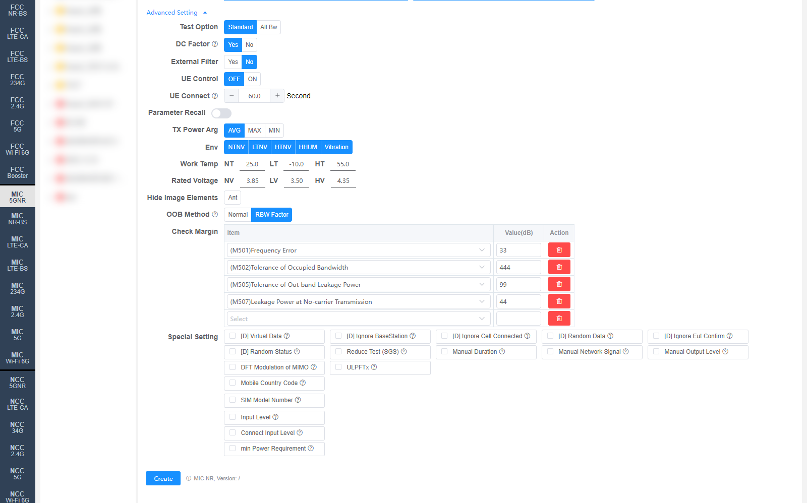
All settings in Advanced Setting can generally be kept at their default values. Adjust them only when the test results are abnormal or there are special test requirements.
DC Factor: Whether to enable duty cycle factor correction. For spurious emission tests.
External Filter: Whether an external filter is used in the RF path, default No.
Parameter Recall: Whether to recall a parameter configuration file stored in the base station emulator.
TX Power Arg: TX power evaluation method: AVG / MAX / MIN.
Env: Environmental conditions, multi-select: NTNV / LTNV / HTNV / HHUM / Vibration.
Work Temp: Temperatures (°C) for the environmental conditions, default NT 25.0 / LT -10.0 / HT 55.0.
Rated Voltage: Voltages (V) for the environmental conditions, default NV 3.85 / LV 3.50 / HV 4.35.
Hide Image Elements: Elements to hide in report images (e.g., the Ant marker).
OOB Method: Measurement method for M505 / M525 Tolerance of Out-band Leakage Power: Normal / RBW Factor. The default value can be changed on the Setting page.
Check Margin: Test margin check. Select an Item and fill in Value(dB); results with a margin smaller than the set value will be flagged.
Special Setting: Special settings. Options prefixed with [D] are debug options:
[D] Virtual Data / [D] Ignore BaseStation / [D] Ignore Cell Connected / [D] Random Data / [D] Ignore Eut Confirm / [D] Random Status: Debug options.
Reduce Test (SGS): Reduced testing (SGS Lite V1).
Manual Duration: Set the Duration manually; the system will not set it for MT8000.
Manual Network Signal: Set the Network Signal manually.
Manual Output Level: Set the Output Level manually.
DFT Modulation of MIMO: Test DFT modulation for MIMO (FCC/MIC 5G NR MIMO).
ULPFTx: When ULPFTx is used, set MIMO parameters UlLayerNum=1 and UlMaxRank=1; else set both to 2.
Mobile Country Code: MCC, range 0-999, default 1. For Anritsu MT8000 / MT8821.
SIM Model Number: SIM card model, default P0250. For MT8000 / MT8821.
Input Level: Input level (dBm).
Corresponding software option: MIC NR