
Creating a Test Plan - CE NR-BS
The CE NR-BS option is used for EU CE (RED) certification testing of 5G NR base station products. Base station testing feeds the test signal via a signal generator (VSG) and measures the output with a spectrum analyzer (SA).
Basic Settings
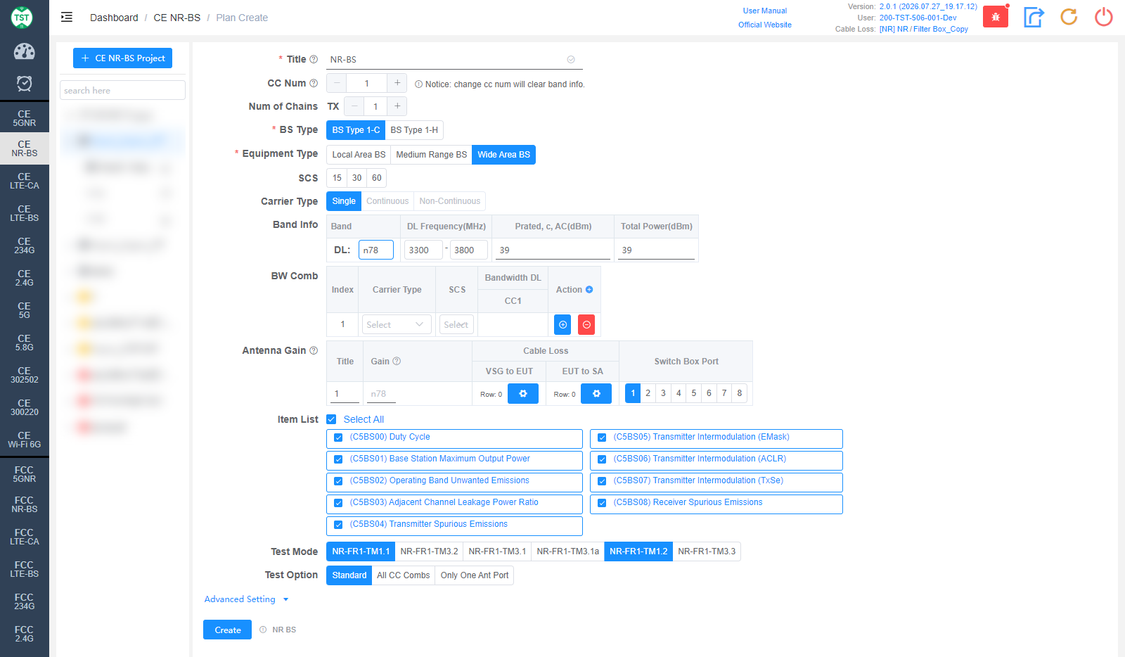
Title: Test plan name, entered by the user.
CC Num: Number of carriers. Note: changing CC Num will clear the Band Info.
Num of Chains: Number of transmit chains (TX).
BS Type: Base station type (required): BS Type 1-C (conducted) / BS Type 1-H (hybrid).
Equipment Type: Base station class (required): Local Area BS / Medium Range BS / Wide Area BS.
SCS: Subcarrier spacings (kHz), multi-select: 15 / 30 / 60.
Carrier Type: Carrier types, multi-select: Single / Continuous / Non-Continuous.
Band Info: NR bands supported by the product:
Band: NR band number, e.g., n1 / n78. The downlink frequency is filled in automatically.
DL Frequency(MHz): Downlink frequency range, auto-filled and editable.
Prated, c, AC(dBm): Rated output power per carrier per antenna connector.
Total Power(dBm): Total output power.
BW Comb: Bandwidth combination table. For each Index, configure Carrier Type / SCS / Bandwidth DL and the bandwidth of each carrier (CC1...); use the +/- icons to add or remove combinations.
Antenna Gain: Antenna gain and cable loss configuration:
Title / Gain: Antenna number and gain (dBi).
Cable Loss - VSG to EUT: Cable loss from the signal generator to the EUT.
Cable Loss - EUT to SA: Cable loss from the EUT to the spectrum analyzer. How to Create Common Cable Loss.
Switch Box Port: Port number of the switch connected to the antenna.
Item List: Test items included in CE NR-BS, all selected by default:
(C5BS00) Duty Cycle
(C5BS01) Base Station Maximum Output Power
(C5BS02) Operating Band Unwanted Emissions (OBUE)
(C5BS03) Adjacent Channel Leakage Power Ratio (ACLR)
(C5BS04) Transmitter Spurious Emissions
(C5BS05) Transmitter Intermodulation (EMask)
(C5BS06) Transmitter Intermodulation (ACLR)
(C5BS07) Transmitter Intermodulation (TxSe)
(C5BS08) Receiver Spurious Emissions
Test Mode: 3GPP NR test models, multi-select: NR-FR1-TM1.1 / TM3.2 / TM3.1 / TM3.1a / TM1.2 / TM3.3. Select according to certification requirements.
Test Option: Test scope: Standard / All CC Combs (test all carrier combinations) / Only One Ant Port.
Continuous Type: Continuous carrier type: Standard / Non-Standard.
Advanced Setting
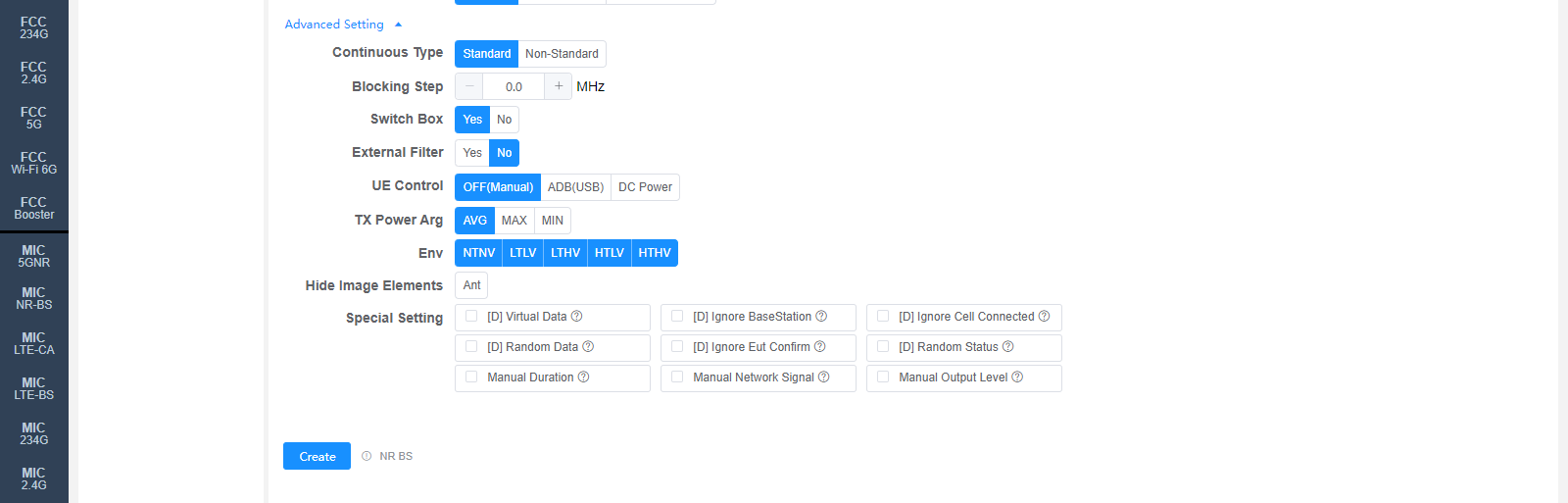
All settings in Advanced Setting can generally be kept at their default values. Adjust them only when the test results are abnormal or there are special test requirements.
Blocking Step: Frequency step (MHz) for the Receiver Blocking test.
Switch Box: Whether to use a Switch Box (RF switch).
External Filter: Whether an external filter is used in the RF path.
UE Control: How to control the sample restart:
OFF(Manual): Manual control, no software control.
ADB(USB): Control the sample via ADB.
DC Power: Restart the sample by switching the DC power supply.
TX Power Arg: TX power evaluation method: AVG / MAX / MIN.
Env: Environmental conditions, multi-select: NTNV / LTLV / LTHV / HTLV / HTHV.
Hide Image Elements: Elements to hide in report images (e.g., the Ant marker).
Special Setting: Special settings. Options prefixed with [D] are debug options:
[D] Virtual Data / [D] Ignore BaseStation / [D] Ignore Cell Connected / [D] Random Data / [D] Ignore Eut Confirm / [D] Random Status: Debug options.
Manual Duration: Set the Duration manually.
Manual Network Signal: Set the Network Signal manually.
Manual Output Level: Set the Output Level manually.
Corresponding software option: NR BS